
Laser printer with reduced banding artifacts

a laser printer and banding technology, applied in the field of laser printers, can solve problems such as gear noise, variable speed of rotation, and imperfect spacing of teeth on the gears

Inactive Publication Date: 2007-09-18
MARVELL INT TECH
View PDF15 Cites 5 Cited by
  • Summary
  • Abstract
  • Description
  • Claims
  • Application Information

AI Technical Summary

Problems solved by technology

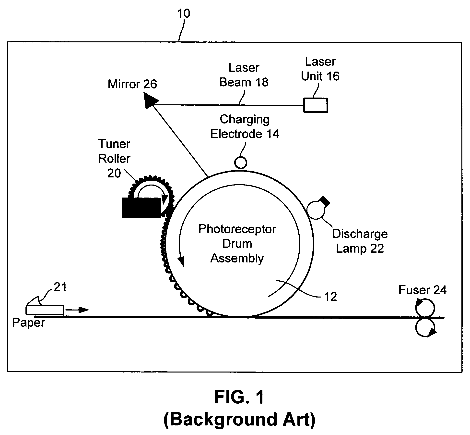
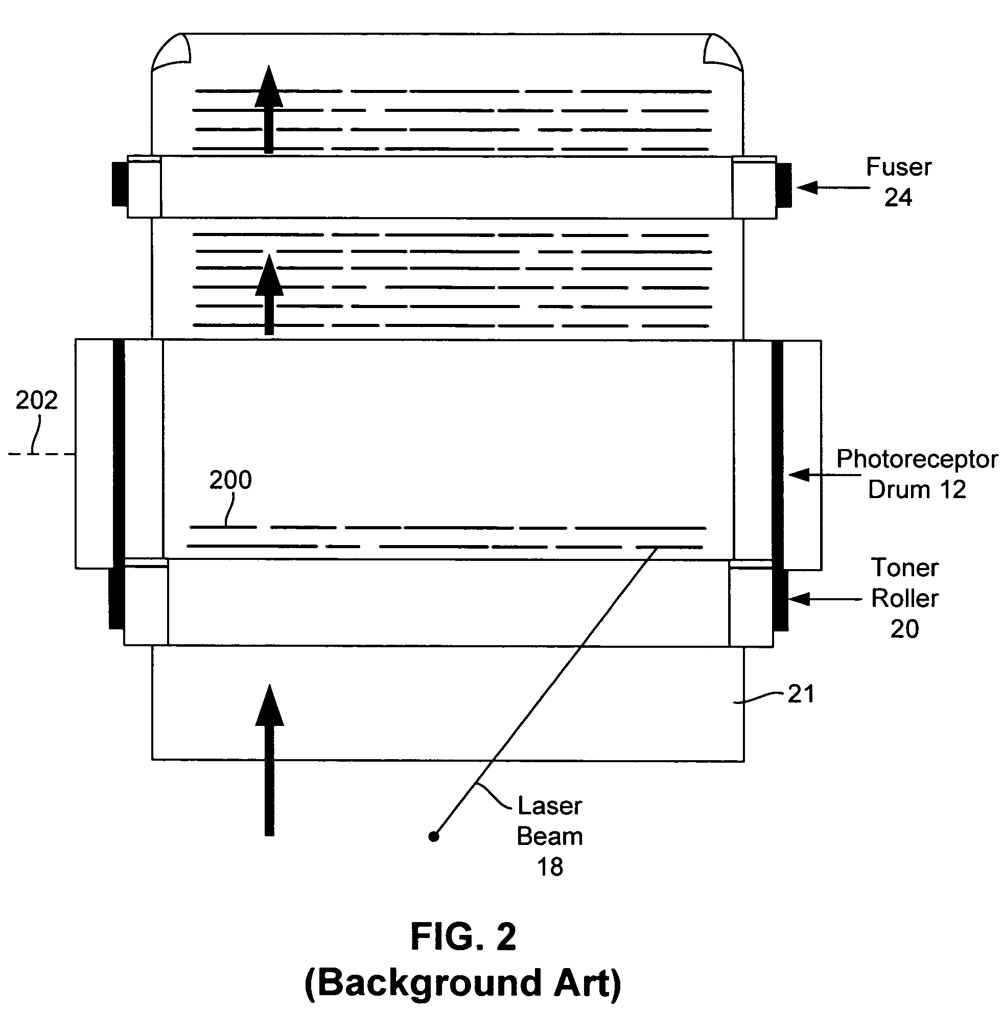
The principle cause of variations in the speed of rotation of the drum 12 and resulting banding is due to gear noise in gears driving the drum.
Gear noise results from imperfect spacing of teeth on the gears, variances in flexing of gear teeth, and other intrinsic variations in gear force transfer.
These approaches, however, can add significantly greater expense to the mechanical components of the printer 10 and thus to the overall cost of the printer.

Method used


Image

  • Laser printer with reduced banding artifacts
  • Laser printer with reduced banding artifacts
  • Laser printer with reduced banding artifacts

Examples


Embodiment Construction

[0022]The following discussion is presented to enable a person skilled in the art to make and use the invention. Various modifications to the preferred embodiment will be readily apparent to those skilled in the art, and the generic principles herein may be applied to other embodiments and applications without departing from the spirit and scope of the present invention as defined by the appended claims. Thus, the present invention is not intended to be limited to the embodiment shown, but is to be accorded the widest scope consistent with the principles and features disclosed herein.

[0023]FIG. 7 is a diagram of an ideal overlapping scan line pattern 700 produced by a laser printer according to a first embodiment of the present invention. The scan line pattern 700 includes a number of scan lines 702-710, with the scan line 704 overlapping the scan lines 702 and 706 and the scan line 708 overlapping the scan lines 706 and 710. The scan lines 702-710 represent the scan lines that a la...


PUM


Abstract

A laser scanning assembly generates a laser beam and scans the laser beam through a plurality of scan lines to form desired dots. Each scan line is positioned to overlap an adjacent scan line and each dot includes a plurality of segments. The scanning assembly scans the laser beam through multiple scan lines to fully discharge each segment of each dot. The laser scanner assembly would typically be part of a laser printer.

Description

BACKGROUND OF THE INVENTION[0001]FIG. 1 shows a typical laser printer 10 including a movable photoreceptor 12, typically a revolving drum or cylinder. This drum 12 is made out of a highly photoconductive material that is discharged by light photons. Initially, the photoreceptor drum 12 is given a total positive charge by a charging electrode 14, typically a wire or roller having a current running through it. As the drum 12 revolves, the printer 10 uses a laser unit 16 (such as a laser diode) to shine a laser beam 18 across the surface of the drum 12 to discharge certain points. In this manner, the laser beam 18“draws” the text and images to be printed as a pattern of electrical discharges (an electrostatic image) on the drum 12. If the laser beam 18 is modulated, resulting variations in charge on the drum 12 will ultimately be translated to proportionate amounts of toner deposited on a sheet of paper 21.[0002]After the laser beam 18 scans the desired electrostatic pattern on the dru...

Claims


Application Information

Patent Timeline
Patent Type & Authority Patents(United States)
IPC IPC(8): B41J2/435B41J2/47G06K1/00
CPCB41J2/47G03G15/754G06K15/1204B41J2/435H04N1/12H04N1/1135H04N2201/0458G06K2215/111B41J2/442B41J2/471G03G15/0275G06K15/1219G06K15/1276
Inventor KEITHLEY, DOUGLAS GENE
Owner MARVELL INT TECH
Learn More