Location estimation of wireless terminals in a multi-story environment

a wireless terminal and multi-story technology, applied in the field of estimating the location of wireless terminals, can solve the problems of insufficient performance of prior art techniques and operating environments

Active Publication Date: 2007-09-18
AVAYA INC
View PDF11 Cites 20 Cited by
  • Summary
  • Abstract
  • Description
  • Claims
  • Application Information

AI Technical Summary

Problems solved by technology

Although some prior art techniques perform well in some operating environments, there are other operating environments in which prior art techniques do not perform adequately.

Method used


Image

  • Location estimation of wireless terminals in a multi-story environment
  • Location estimation of wireless terminals in a multi-story environment
  • Location estimation of wireless terminals in a multi-story environment

Examples


Embodiment Construction

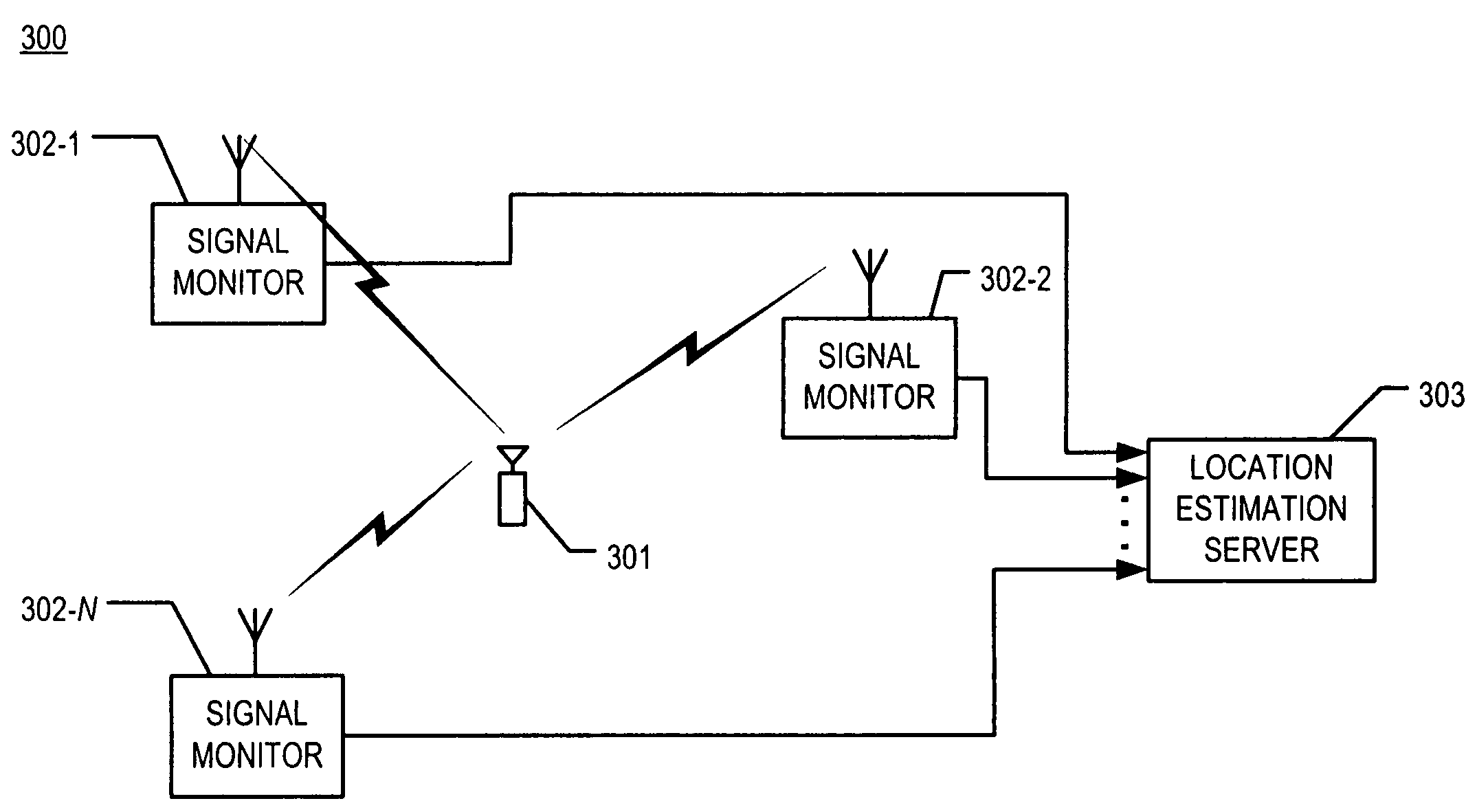
[0018]FIG. 3 depicts a schematic diagram of network 300 comprising the components of the illustrative embodiment of the present invention. Network 300 operates in accordance with a set of air interface protocols (e.g., IEEE 802.11, etc.) and comprises wireless terminal 301; signal monitors 302-1 through 302-N, wherein N is a positive integer; and location estimation server 303, interconnected as shown.

[0019]Wireless terminal 301 is capable of transmitting packets of data over a wireless medium in well-known fashion. The packets of data can comprise information that identifies wireless terminal 301. Wireless terminal 301 can be a communications station, a locating device, a handheld computer, a laptop with wireless capability, a telephone, etc. It will be clear to those skilled in the art how to make and use wireless terminal 301.

[0020]In some embodiments, wireless terminal 301 exchanges packets with an access point (not shown). In some other embodiments, wireless terminal 301 transm...


PUM


Abstract

A method and apparatus are disclosed for estimating the location of a wireless terminal across multiple building floors. The illustrative embodiment determines the floor where the wireless terminal is presently located by using a majority logic-based heuristic. A plurality of signal monitors measure signals from the wireless terminal and provide those signal strength measurements to a location estimation server. Alternatively, the wireless terminal measures signals that are transmitted by a plurality of transmitting signal devices and provides those signal strength measurements to a location estimation server. The location estimation server determines the floor of the wireless terminal in accordance with the illustrative embodiment of the present invention.

Description

FIELD OF THE INVENTION[0001]The present invention relates to telecommunications in general, and, more particularly, to estimating the location of a wireless terminal.BACKGROUND OF THE INVENTION[0002]FIG. 1 depicts a schematic diagram of wireless network 100 in the prior art, which comprises wireless telecommunication terminal 101 and access points 102-1 through 102-L, interconnected as shown. Wireless terminal 101 uses access points 102-1 through 102-L to exchange blocks of data, or “packets,” with computer servers that are external to wireless network 100. At any given time, wireless terminal 101 is associated with one of access points 102-1 through 102-L for the purpose of communicating with the external servers.[0003]It is important in some operating scenarios to know the location of wireless terminal 101 within wireless network 100. Knowing the location enables, for instance, services that use end-user location information. Such services include location-aware content delivery, ...

Claims


Application Information

Patent Timeline
Patent Type & Authority Patents(United States)
IPC IPC(8): H04Q7/20G01S19/19H04L12/28H04L12/56H04W24/00H04W64/00
CPCG01S5/02H04W64/00H04W24/00G01S5/0295G01S5/0252G01S5/021G01S5/04H04W4/029
Inventor KRISHNAKUMAR, ANJUR SUNDARESANKRISHNAN, P
Owner AVAYA INC
Why Eureka
Try Eureka