
Diagnostic device for a fluidic device and a fluidic device equipped therewith

a fluidic device and diagnostic device technology, applied in the direction of flow control, hardware monitoring, instruments, etc., can solve the problems of diagnostic device reporting a fault in the fluidic device, the failure of the fluidic device, and the difficulty in ascertaining the optimum maintenance timepoint, so as to reduce the operating speed of the pneumatic working cylinder

Inactive Publication Date: 2007-09-18
BECK IPC +1
View PDF10 Cites 27 Cited by
  • Summary
  • Abstract
  • Description
  • Claims
  • Application Information

AI Technical Summary

Benefits of technology

[0019]Preferably the diagnostic device is equipped to execute an emergency program so that additional wear during continued operation of the fluidic device...

Problems solved by technology

A fluidic device, for example, a pneumatic valve array, is subject to wear during use, which will adversely impact its operational dependability to an increasing extent over time, and ultimately lead to malfunction or even to complete failure of the fluidic device.
If a malfunction or failure has occurred, the fluidic device will then have to be repaired or replaced by an intact fluidic device.
However, it is difficult to ascertain an optimum maintenance timepoint, since this moment in time can depend on many factors, in particular on the particular strain on the fluidic device caused by its operation.
The diagnostic device then reports a fault in the fluidic device, for example, when its actuator element is no longer capable of movement and / or when overheating has occurred.

Method used


Image

  • Diagnostic device for a fluidic device and a fluidic device equipped therewith
  • Diagnostic device for a fluidic device and a fluidic device equipped therewith
  • Diagnostic device for a fluidic device and a fluidic device equipped therewith

Examples


Embodiment Construction

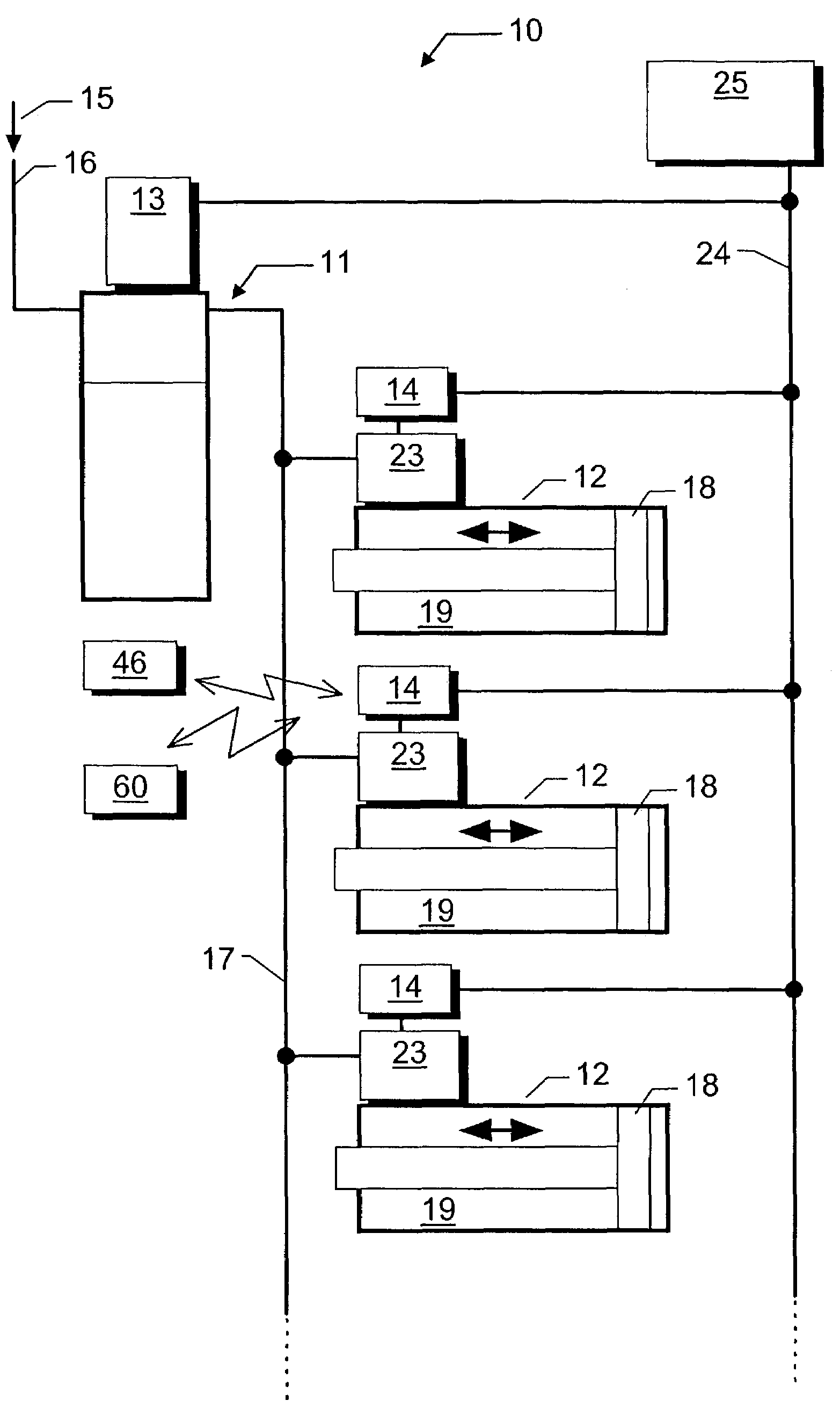
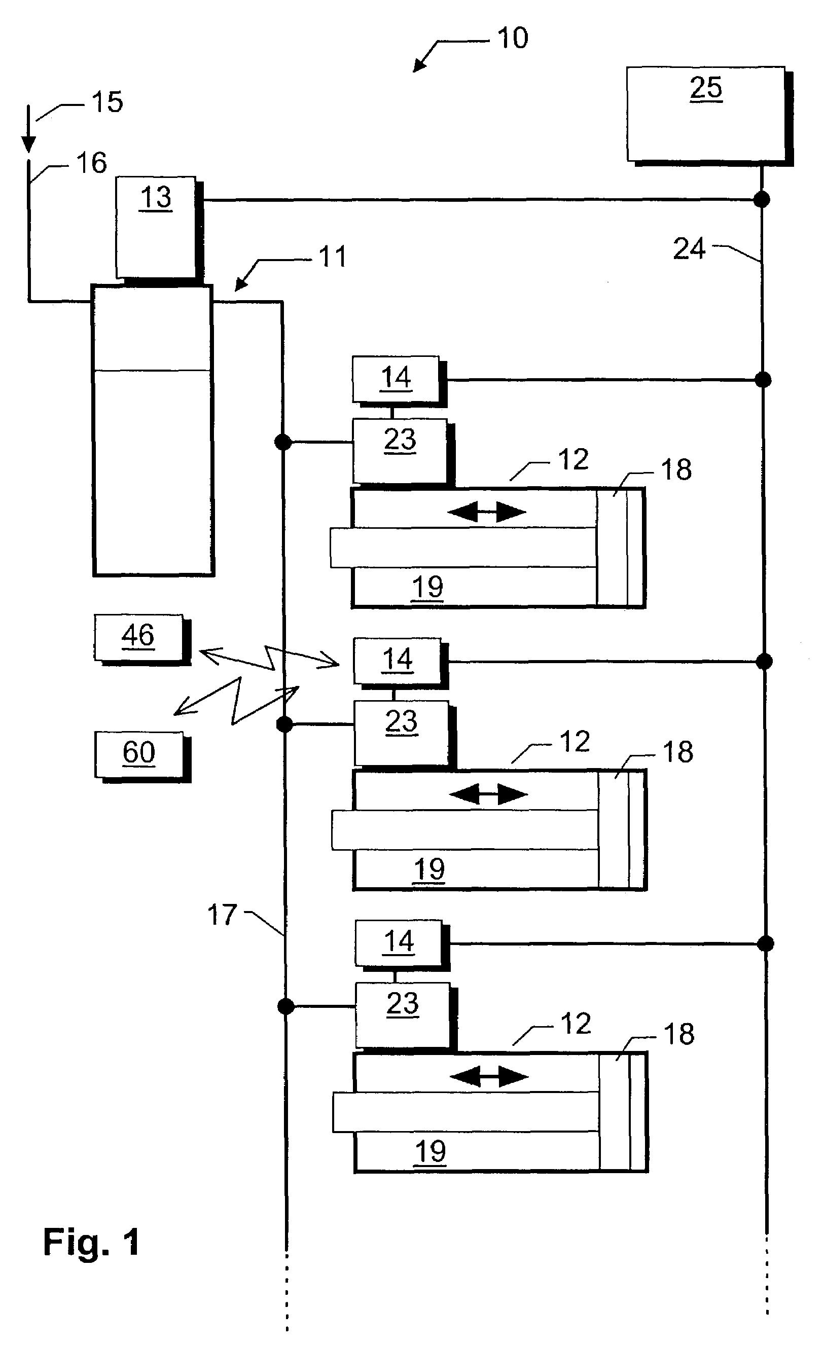
[0027]In the present case the fluidic device 10 pertains to a pneumatic device with several fluidic actuators upstream of the working cylinders 12. The device 10 is used, for instance, to drive a handling machine or similar unit. The device 10 is supplied with a compressed medium 15, in this case, compressed air, by a compressed air supply device (not illustrated). The compressed medium 15 is injected through a supply line 16 into the maintenance unit 11 which processes the compressed medium, e.g., by cleaning it and / or oiling it. The filters or additives, e.g., oil or such, needed for this are not shown in the illustration for the sake of simplification. In any case, the maintenance unit 11 supplies the working cylinder 12 with the treated compressed medium—in the present case, cleaned and oiled compressed air—15 through a supply line 17.

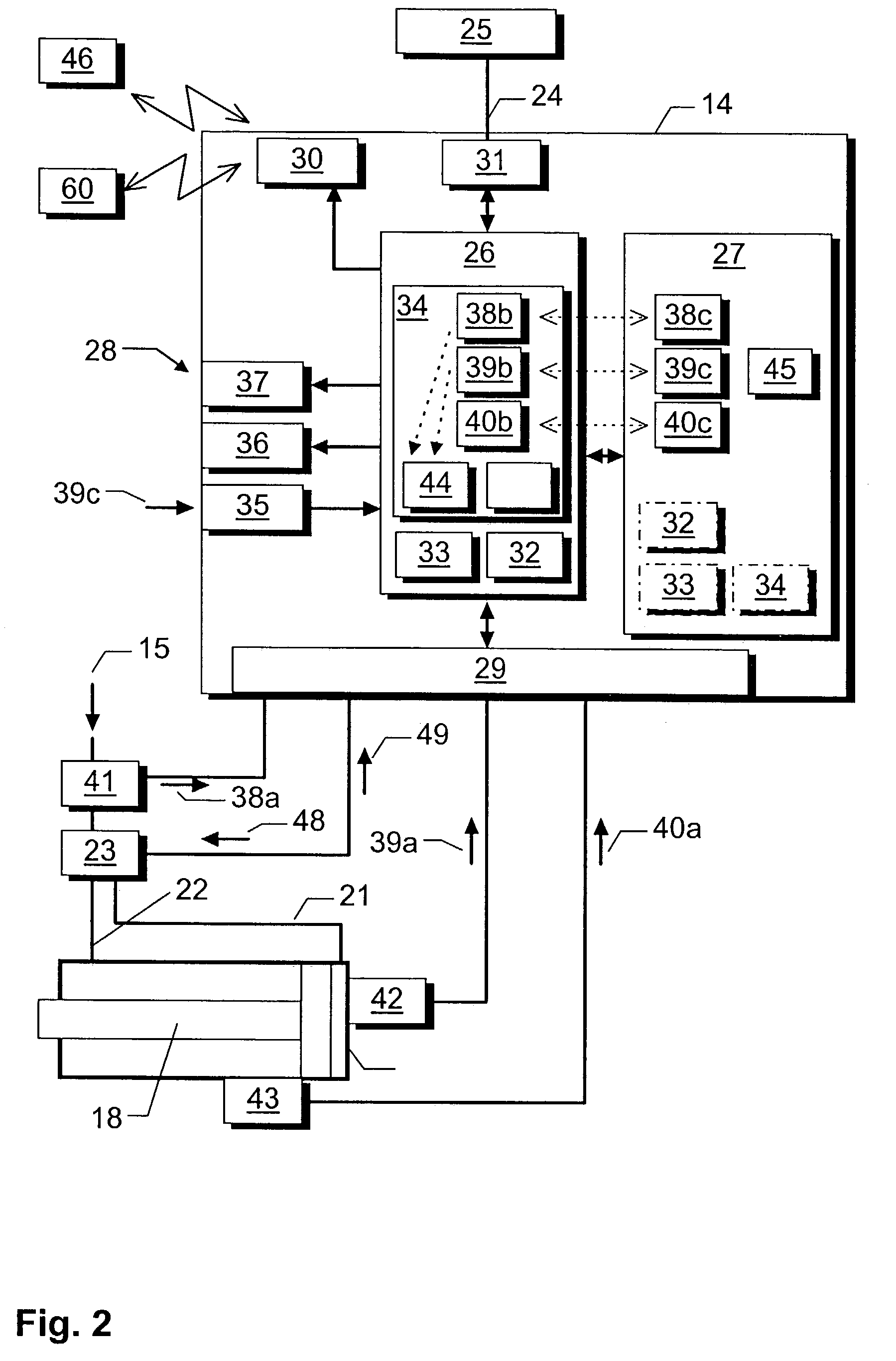
[0028]A piston 18 forming the actuator element is seated in a piston chamber 19 and moves back and forth in the working cylinder 12 which each for...


PUM


Abstract

The invention pertains to a diagnostic device for a fluidic device (11, 12, 23), in particular for a valve array and or a maintenance unit. Furthermore, the invention pertains to a fluidic device (11, 12, 23) equipped with said diagnostic device. The diagnostic device preferably can be locally attached to the fluidic device (11, 12, 23). It features a diagnostic module (34) to determine at least one wear parameter (38b-40b,44) causing wear on the fluidic device (11,12,23) and for reporting of at least one wear status ascertained on the basis of the at least one wear parameter (38b-40b,44).

Description

[0001]The application claims priority from Application No. DE 201 20 609.9, filed on Dec. 20, 2001.FIELD OF INVENTION[0002]The invention pertains to a diagnostic device for a fluidic device, in particular for a valve array, a fluidic actuator or a maintenance unit. Furthermore, the invention pertains to a fluidic device equipped with said diagnostic device.BACKGROUND OF THE INVENTION[0003]A fluidic device, for example, a pneumatic valve array, is subject to wear during use, which will adversely impact its operational dependability to an increasing extent over time, and ultimately lead to malfunction or even to complete failure of the fluidic device. If a malfunction or failure has occurred, the fluidic device will then have to be repaired or replaced by an intact fluidic device. However, it is often better from a cost point of view to prevent the malfunction or complete failure by providing advance maintenance of the fluidic device in a timely manner.[0004]However, it is difficult t...

Claims


Application Information

Patent Timeline
IPC IPC(8): G06F11/30G21C17/00F15B19/00
CPCF15B19/005
Inventor SCHLOSSER, ERNEST
Owner BECK IPC
Features
  • Generate Ideas
  • Intellectual Property
  • Life Sciences
  • Materials
  • Tech Scout
  • Unparalleled Data Quality
  • Higher Quality Content
  • 60% Fewer Hallucinations
Learn More