
Vehicle suspension apparatus

a technology of suspension apparatus and vehicle, which is applied in the direction of electric propulsion mounting, transportation items, loading/unloading vehicle arrangment, etc., can solve the problems of poor mechanical advantage, logistics burden, and bulky traditional trailing arm suspension system, and achieves significant space and space requirements

Inactive Publication Date: 2007-09-25
GENERAL DYNAMICS LAND SYSTEMS
View PDF24 Cites 17 Cited by
  • Summary
  • Abstract
  • Description
  • Claims
  • Application Information

AI Technical Summary

Benefits of technology

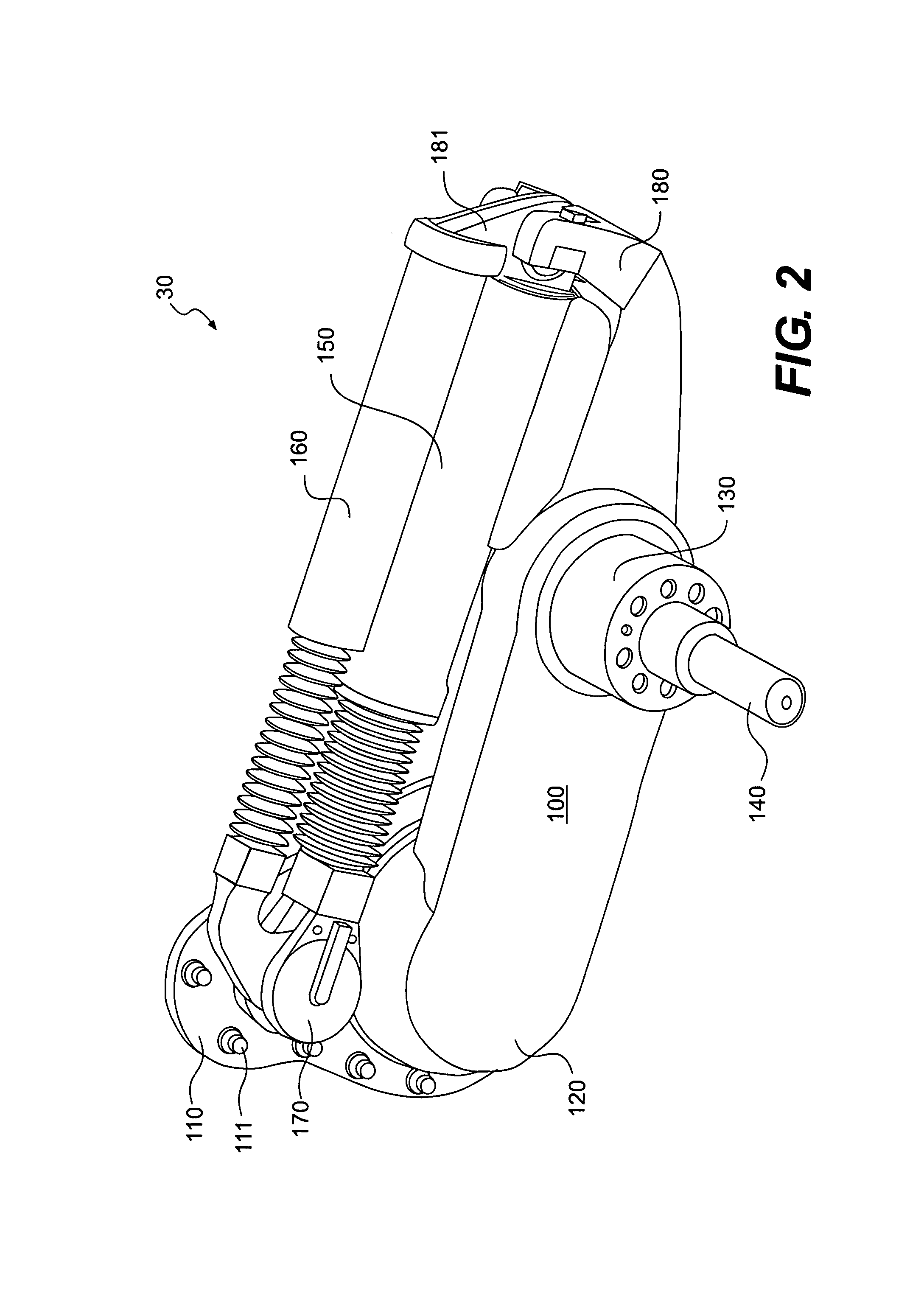
"The present invention is a suspension system for vehicles that includes a trailing arm element, a spring element, and a damper element. These components are positioned external to and above the trailing arm element. The suspension system also includes a ring bearing and a mounting plate that are rotationally connected by the ring bearing. The mounting plate is symmetrical about at least one axis. The suspension system may also include a plurality of supply lines, a wheel assembly, and a spindle. The technical effects of this invention include improved vehicle stability, reduced vibration, and improved ride quality."

Problems solved by technology

Shocks and springs act on the swing arm to control the characteristics of the suspension system and are located within the swing arm or trailing arm, resulting in poor mechanical advantage.
Unfortunately, a notable logistics burden results from the use of nitrogen when the vehicle is far from home or a ready source of pressurized nitrogen.
Traditional trailing arm suspension systems are also bulky and require significant space to accommodate the structure requirements of the trailing arm suspension.
The mounting plates of traditional trailing arm suspensions require precious needed space between the wheel and the hull of the vehicle to connect large bearing flanges on hollow or ring bearings.
The mounting plates are also expensive to employ because of the need to manufacture separate plates for different positions and on different sides of the hull of the vehicle.
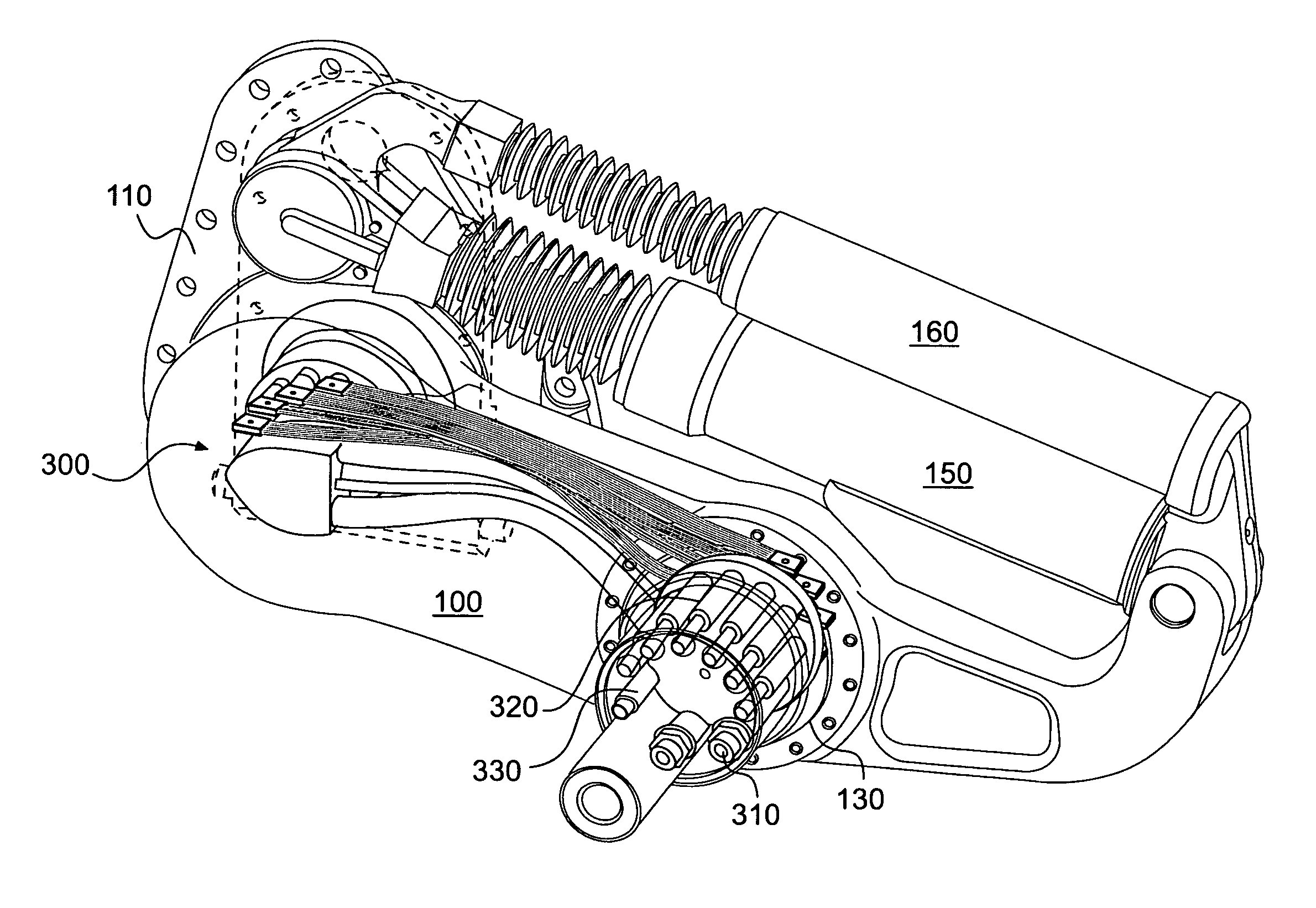
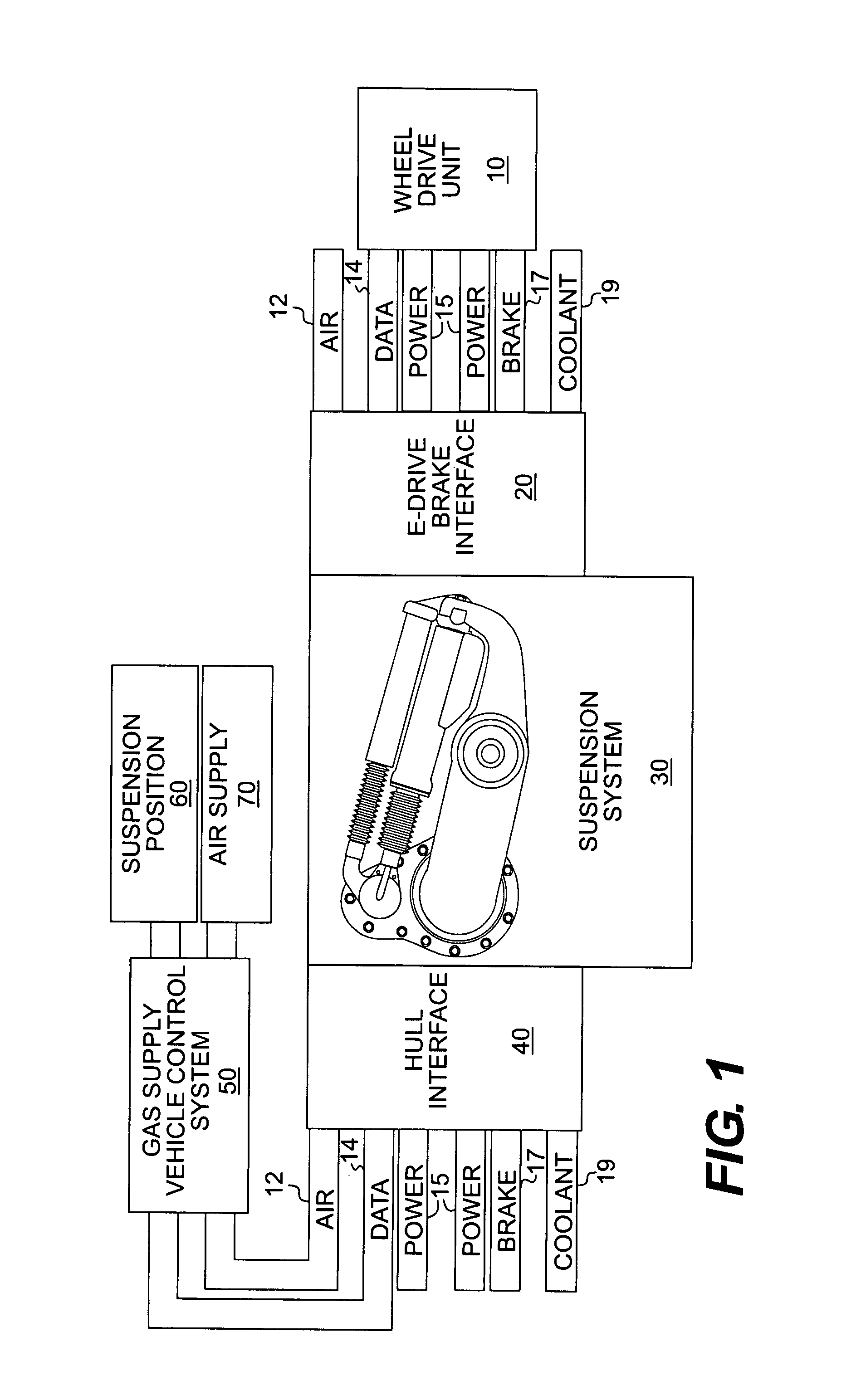
Traditional trailing arm suspension systems also lack efficient connection systems for electrical, coolant, and mechanical connections that are protected between the hull and the wheel and do not leak fluids.
For electrical drive applications, traditional systems do not provide direct plug-in connectors for cables while allowing flexing during arm rotation and vertical wheel movement.

Method used


Image

  • Vehicle suspension apparatus
  • Vehicle suspension apparatus
  • Vehicle suspension apparatus

Examples


Embodiment Construction

[0025]For simplicity and illustrative purposes, the principles of the present invention are described by referring mainly to the exemplary embodiment thereof. However, one of ordinary skill in the art would readily recognize that the same principles are equally applicable to, and can be implemented in, many types of systems involving trailing arm suspensions or other similar devices, and that any such variations do not depart from the true spirit and scope of the present invention. Moreover, in the following detailed description, references are made to the accompanying figures, which illustrate specific embodiments. Electrical, mechanical, logical and structural changes may be made to the embodiments without departing from the spirit and scope of the present invention. The following detailed description is, therefore, not to be taken in a limiting sense and the scope of the present invention is defined by the appended claims.

[0026]An embodiment of the invention generally relates to ...


PUM


Abstract

A trailing arm suspension unit for use on a vehicle including a ring bearing, a trailing arm, a spring and damper for providing large vertical wheel travel in a jounce and rebound suspension condition. The ring bearing may include external threads for rotationally connecting the trailing arm to a mounting plate or a hull of the vehicle. Further, supply lines for electrical and fluids may be passed through the opening in the ring bearings without the use of a slip ring and passed through a passage in the trailing arm to a wheel on the vehicle. The spring and damper may be located on top of the trailing arm and separately connected to the mounting plate to generate significant mechanical advantage. The geometry of the spring, damper, and trailing arm allow the spring in the suspension unit to be gas cylinder employing air.

Description

CROSS REFERENCE TO RELATED APPLICATIONS[0001]This application takes priority from U.S. non-provisional application Ser. No. 60 / 470,436 filed May 15, 2003, which provisional application is herein incorporated by reference.BACKGROUND OF THE RELATED ART[0002]This invention relates generally to vehicle suspension systems, and more particularly to an external trailing arm pneumatic suspension with integral accommodations for electric or gear driven wheel ends.[0003]Conventional trailing arm suspension devices are known and used in vehicles designed for rugged terrain and severe conditions. For example, trailing arm suspensions have long been used on tanks, providing long vertical travel suspension for use under military conditions. A single unit of a trailing arm suspension system typically includes a mounting plate connecting a swing arm to a hull of a vehicle and a hub or wheel spindle at the end of the swing arm for connecting a wheel to the suspension system. Shocks and springs act o...

Claims


Application Information

Patent Timeline
Patent Type & Authority Patents(United States)
IPC IPC(8): B60G3/12B60K1/00B60G3/14B60G7/02B60G15/12B62D61/12
CPCB60G3/145B60G7/02B60G15/12B60G2200/132B60G2200/422B60G2204/128B60G2204/13B60G2204/143B60G2204/30B60G2204/418B60G2206/0114B60G2300/07
Inventor POND, JAMES
Owner GENERAL DYNAMICS LAND SYSTEMS
Learn More