
Electronic breakaway device

a technology of electronic breakaway and battery, which is applied in the direction of automatic initiation, braking system, transportation and packaging, etc., can solve the problems of out of control towed vehicle and may no longer receive the signals of towed vehicle, and achieve the effect of quick draining of battery

Active Publication Date: 2007-09-25
HOPKINS MFG
View PDF18 Cites 28 Cited by
  • Summary
  • Abstract
  • Description
  • Claims
  • Application Information

AI Technical Summary

Benefits of technology

The present invention provides a breakaway device that automatically engages a towed vehicle's brakes when it separates from the towing vehicle. This device is part of a wiring harness that allows equipment mounted on the towed vehicle to be operated by signals received from the towing vehicle. The device uses a metal-oxide semiconductor field-effect transistor (MOSFET) or an electro-mechanical switch to detect the separation and engage the brakes. An override is included to prevent current flow and allow for repositioning of the towed vehicle. The device provides a visual indication of whether the brakes are engaged and is fail-safe to ensure safety and reliability.

Problems solved by technology

For example, if the towed vehicle separates from the towing vehicle, the towed vehicle would be out of control and may no longer receive the signals from the towing vehicle.

Method used


Image

  • Electronic breakaway device
  • Electronic breakaway device
  • Electronic breakaway device

Examples


first embodiment

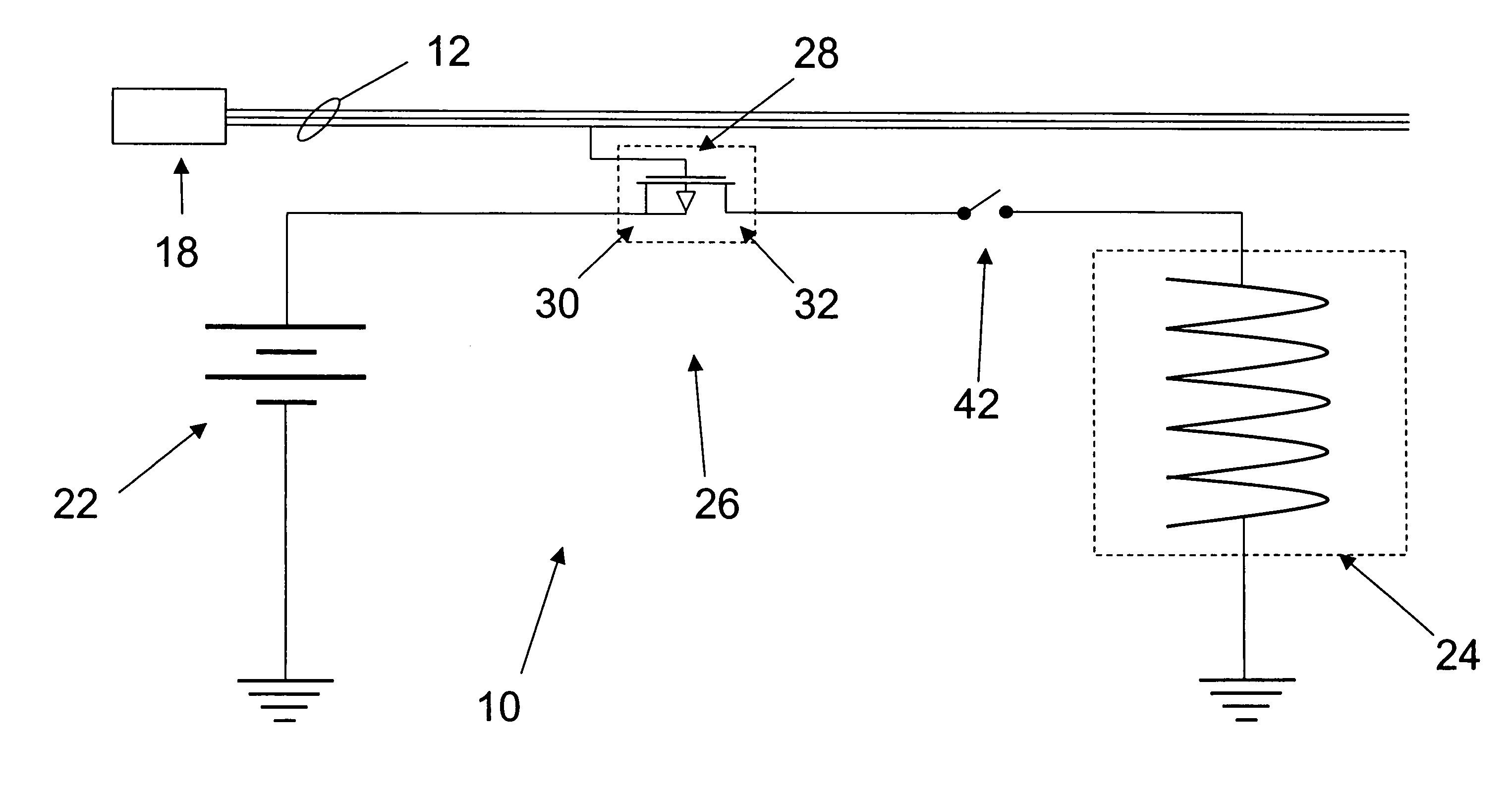
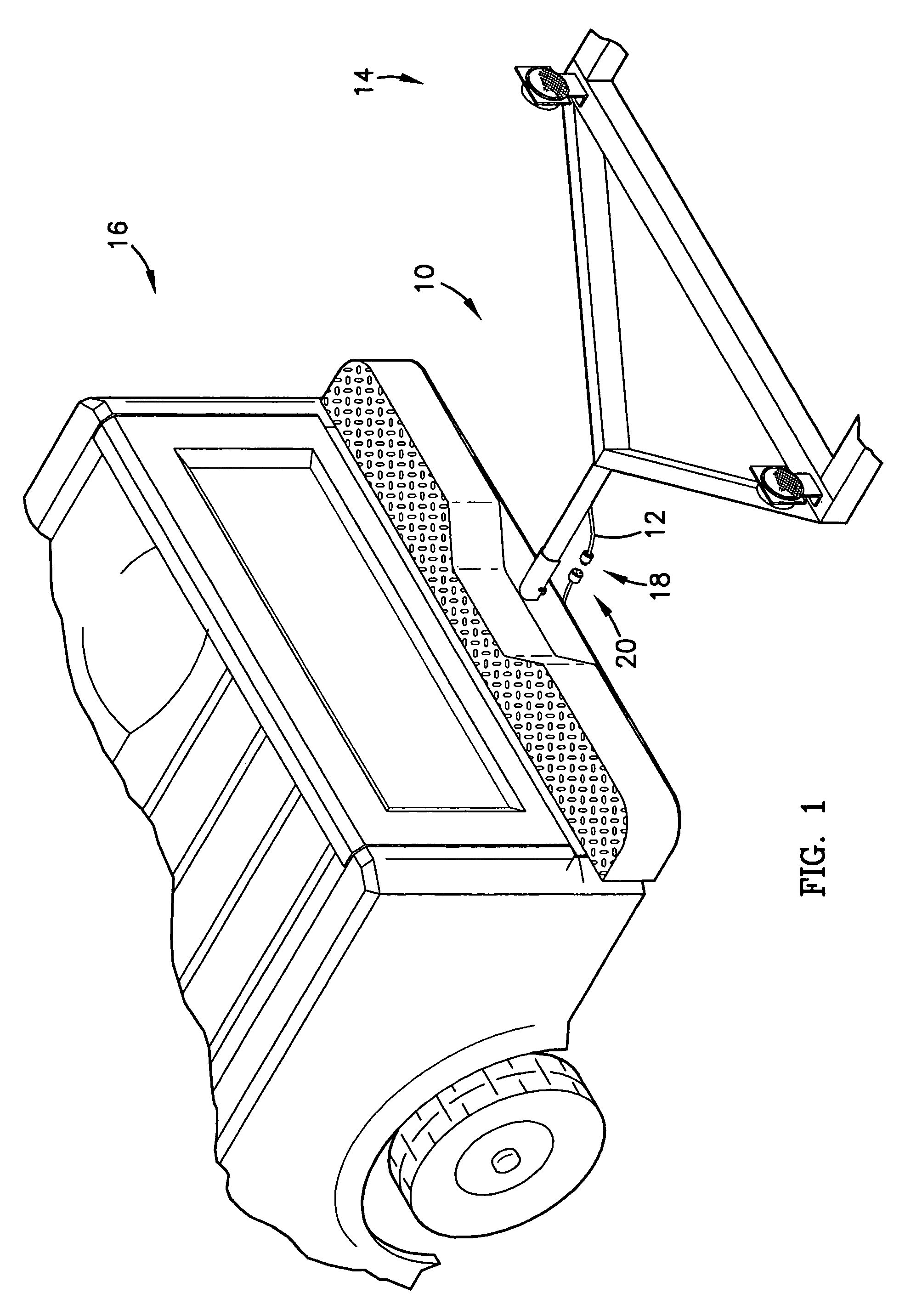
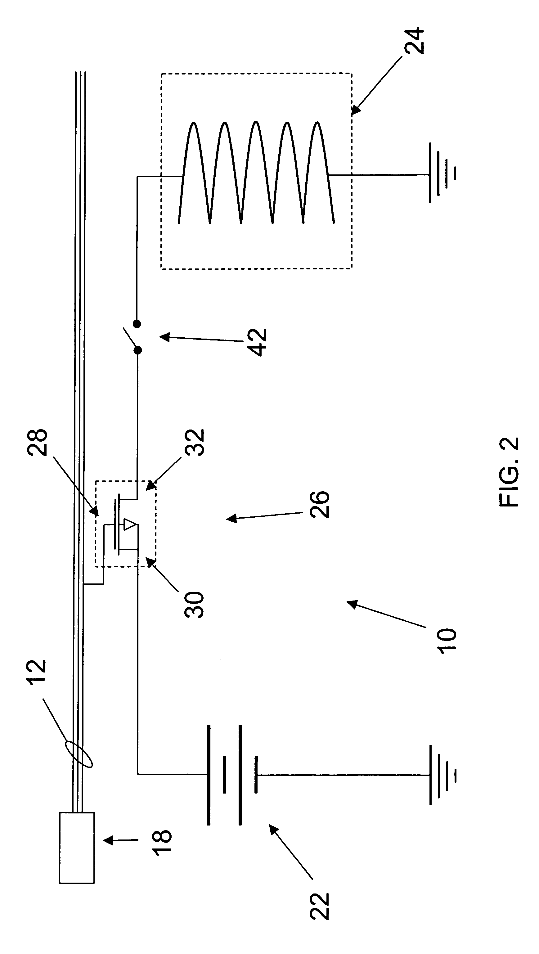
[0026]The device 10 is designed to detect when the towed vehicle 14 has separated from the towing vehicle 16 and then engage the brakes. A preferred first embodiment of the device 10 comprises a metal-oxide semiconductor field-effect transistor (MOSFET) 26. A gate 28 of the MOSFET 26 is preferably electrically coupled to a signal received from the towing vehicle 16 that is expected to be energized at all times. For example, an auxiliary power signal received from the towing vehicle 16 and used to substantially continuously provide power to the towed vehicle 14 may also be used to energize the gate 28, while the towed vehicle 14 is connected to the towing vehicle 16. With the gate 28 energized in this manner, the MOSFET 26 prevents current flow from the battery 22 to the solenoid 24.

[0027]If the towed vehicle 14 becomes separated from the towing vehicle 16, the harness 12 will pull the plug 18 from the socket 20. In this manner, the auxiliary power signal will be lost and the gate 28...

second embodiment

[0029]Referring also to FIG. 3, a preferred second embodiment of the device 10 comprises an electro-mechanical switch 34. A coil 36 of the switch 34 is preferably electrically coupled to the auxiliary power signal received from the towing vehicle 16. For example, the coil 36 may be wired either in series or parallel with the auxiliary power signal to the towed vehicle 14. In either case, the coil 36 is preferably energized whenever the auxiliary power is energized. With the coil 36 energized in this manner, the switch 34 is held open preventing current flow from the battery 22 to the solenoid 24.

[0030]If the harness pulls the plug 18 from the socket 20, the auxiliary power signal will be lost and the coil 36 will become de-energized. With the coil 36 de-energized, the switch 34 closes allowing current to flow from the battery 22 to the solenoid 24, thereby engaging the brakes and decelerating the towed vehicle 14. More specifically, a first contact 38 of the switch 34 may be electri...


PUM


Abstract

A breakaway device (10) to detect when a towed vehicle (14) separates from a towing vehicle (16) in order to engage the towed vehicle's brakes broadly comprises a sensor operable to detect when a signal from the towing vehicle (16) is lost and a shunt operable to route electrical power to the brakes. In a preferred embodiment, the sensor and the shut may be embodied in a transistor (26). In an alternative embodiment, the sensor and the shut may be embodied in an electro-mechanical switch (34). The device (10) preferably includes an override (42) and lights (44,46) to indicate the device's (10) status.

Description

BACKGROUND OF THE INVENTION[0001]1. Field of the Invention[0002]The present invention relates to breakaway devices. More particularly, the present invention relates to a breakaway device that can automatically and reliably engage a towed vehicle's brakes when the towed vehicle separates from a towing vehicle.[0003]2. Description of Prior Art[0004]Towed vehicles, such as trailers, are often heavily loaded and towed behind towing vehicles, such as trucks. Occasionally, a trailer will break away and become separated from a truck. When this happens, the trailer becomes out of control and presents a serious hazard to the trailer's contents, as well as other vehicles in the road. Therefore, many trailers include electrically operated brakes and batteries to power the brakes in the event they become uncontrolled.[0005]Such systems typically use plunger switches to engage the brakes. Plunger switches typically consist of two contacts physically held apart by a plunger. When a plunger is pul...

Claims


Application Information

Patent Timeline
Patent Type & Authority Patents(United States)
IPC IPC(8): B60T7/20B60T17/18
CPCB60T7/20B60T17/18
Inventor GRAY, JONATHAN S.
Owner HOPKINS MFG
Learn More