Thin-film deposition apparatus

a thin film deposition and apparatus technology, applied in chemical vapor deposition coatings, coatings, metallic material coating processes, etc., can solve the problems of difficult to efficiently purge the gas, insufficient, and impede the purging of reaction gas from the showerhead, so as to achieve the effect of preventing the clogging of reaction gas

Active Publication Date: 2007-09-25
ASM JAPAN
View PDF6 Cites 92 Cited by
  • Summary
  • Abstract
  • Description
  • Claims
  • Application Information

AI Technical Summary

Benefits of technology

[0005]In the showerhead system, a precursor can be fed onto a substrate at a uniform concentration distribution or at a prescribed concentration distribution. To achieve a uniform concentration distribution, controlling of conductance from the showerhead to the substrate by a distribution plate is necessary, which triggers hindering of reaction gas purging from the showerhead. Because at least two different reaction gases are fed alternately, after Reaction Gas A is fed, Reaction Gas B often can be fed only after purging Reaction Gas A is completed. Thus, an approach to feed Reaction Gas A and Reaction Gas B uniformly from the showerhead via different gas paths, hence, is effective, wherein Reaction Gas A and Reaction Gas B are made to react only on a substrate surface.
[0006]Additionally, as another approach to quickly purge Reaction Gases A and B from the showerhead respectively, an exhaust port is provided on at least one side to evacuate the inside of the showerhead in a short period of time during gas purging. This method is able to solve a problem, which conventionally hinders atomic layer deposition by the showerhead.
[0008]In view of the foregoing, in an embodiment, the present invention provides a gas-feeding apparatus configured to be connected to an evacuatable reaction chamber provided with a support for placing a substrate thereon, comprising: a gas-distribution head for introducing gases into the chamber through a head surface, which gas-distribution head comprises a first section for discharging a gas through the head surface toward the support and a second section for discharging a gas through the head surface toward the support, said first and said second sections being isolated from each other in the gas-distribution head, at least one of which section is coupled to an exhaust system for exhausting a gas present in the corresponding section without passing through the head surface. In the above embodiment, the gas-feeding apparatus comprises multiple gas lines or systems, at least one of which is coupled to an exhaust system, so that multiple gases can be used very efficiently due to rapid or instant purging operation. The gas present in the section can be purged without passing through the head surface, e.g., a showerhead lower surface having a plurality of bores. A low-vapor pressure primary material and a low molecular weight secondary material can be effectively used.
[0012]In yet another embodiment, the present invention is characterized in that a showerhead used for, e.g., atomic layer growth processing by feeding two or more different gases alternately has two or more separate gas-distribution paths, and that a means for exhausting the inside of the showerhead, which is communicated with at least one gas-distribution path. Additionally, in this embodiment, a plasma can be generated either between the showerhead and a substrate surface, or inside the showerhead. Additionally, in an embodiment, when a plasma is generated, the present invention may be characterized in that a gas-distribution portion not communicated with an exhaust path is at least provided on the substrate side, rather a gas-distribution portion communicated with the exhaust path is provided. Even if the gas-distribution portion not communicated with an exhaust path is provided on the substrate side, it is possible to make it communicated with an exhaust path disposed downstream of the showerhead. Providing an exhaust path on a side which is more remote from a substrate than the other side, however, makes the path more efficient, hence advantageous. This may be because it is difficult to feed a low-vapor-pressure material gas under high pressure, and to introduce a low-vapor-pressure material gas into the showerhead under relatively low pressure, a sufficient capacity or space for diffusing the gas may be required. For this purpose, in an embodiment, providing a distribution chamber with a larger capacity on the side away from the substrate is advantageous. Additionally, because this structure allows the gas to be introduced to the center of the chamber, the gas can be distributed more uniformly.
[0013]As described above, using a post-mixing type showerhead, a thin-film deposition apparatus according to an embodiment of the present invention is able to feed material gases extremely uniformly while vapor-phase reaction of material gases having high reactivity is controlled by setting up a dedicated exhaust port with a valve which opens / closes rapidly, or a variable conductance valve in respective gas-distribution chambers, wherein purging the remaining gas can be completed at high speeds, e.g., in about 10 msec to about 500 msec (including 25 msec, 50 msec, 100 msec, 200 msec, 300 msec, and ranges of any two of the foregoing, preferably about 50 msec to about 100 msec), depending on the conductance of the exhaust system. Conventionally, evacuating the reaction gas remaining inside the showerhead in a short period of time was not feasible. Consequently, in an embodiment of the present invention, it becomes possible to form a uniform thin film with high productivity rates, which never could be achieved before, and with no or fewer particles. Additionally, in the case of a reaction, which becomes chemically active only when RF is applied to one of gases, stopping plasma application stops the reaction, hence no purging is required for the one of gases. In this case, by setting up a dedicated exhaust port and an exhaust valve only in a distribution chamber to which a metal material gas is introduced, a thin film can be formed extremely efficiently.

Problems solved by technology

To achieve a uniform concentration distribution, controlling of conductance from the showerhead to the substrate by a distribution plate is necessary, which triggers hindering of reaction gas purging from the showerhead.
In US 2003 / 0143328A1, although the feeding of a low-vapor-pressure material gas and the feeding of any other material gases are conducted through respective different paths, the low-vapor-pressure material gas is discharged from a lower portion provided facing a substrate surface (the gases for plasma generation are provided in an upper portion above the lower portion), and thus there is not a sufficient space to distribute the gas symmetrically with respect to the center point of a wafer, and furthermore it is difficult to purge the gas efficiently (no separate exhaust system is provided).

Method used


Image

  • Thin-film deposition apparatus
  • Thin-film deposition apparatus
  • Thin-film deposition apparatus

Examples


process examples

[0068]Specific examples are shown below, but the present invention should not be limited thereto.

example 1

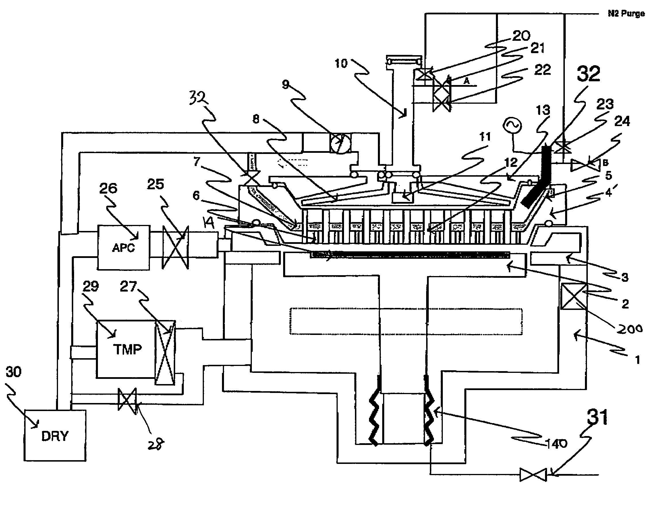
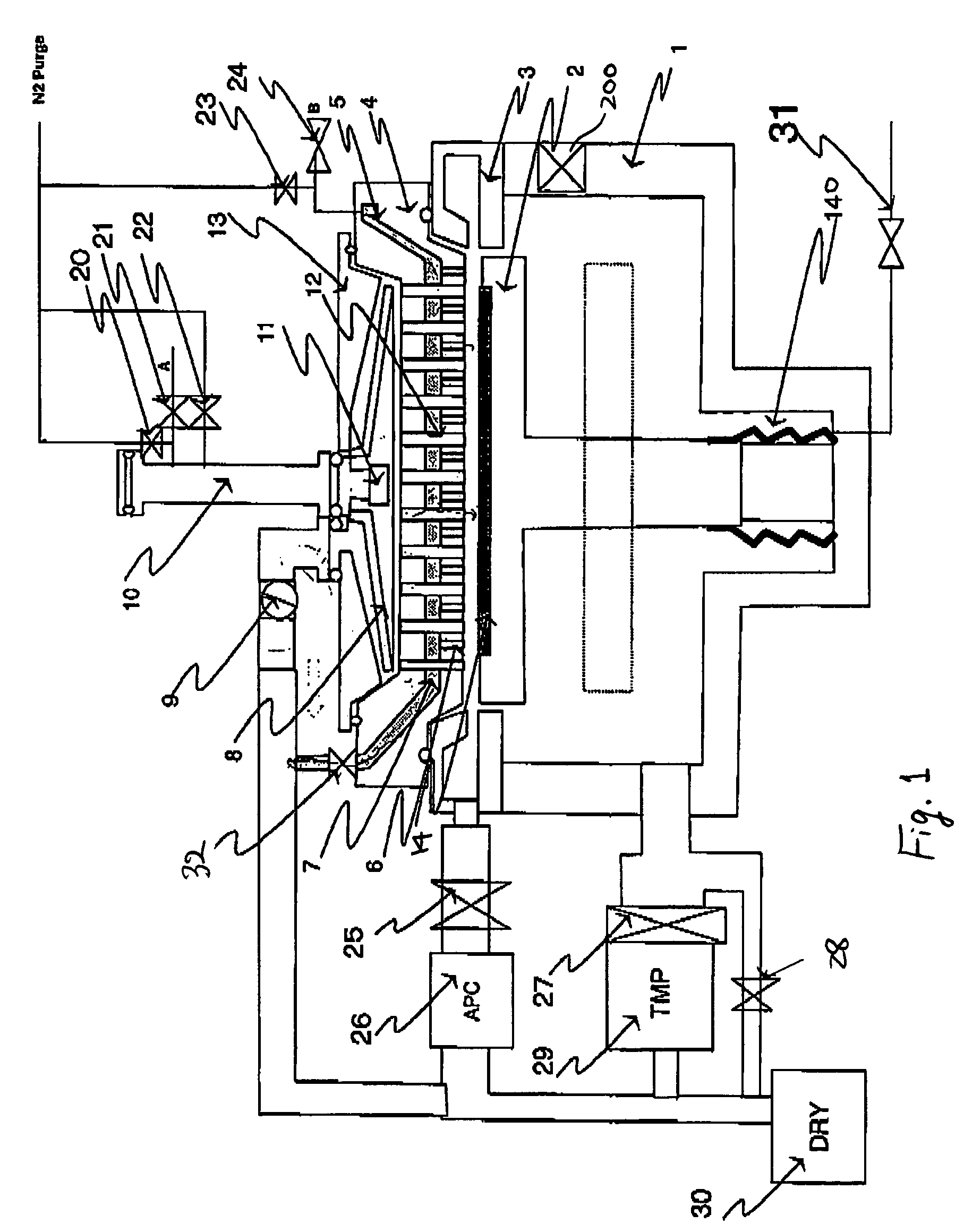
[0069]An example of implementing a specific process using the process apparatus having the structure shown in FIG. 1 is demonstrated; a process of depositing a TiN film using titanium tetrachloride (TiCl4) and ammonia (NH3) as material gases is demonstrated. After a silicon substrate is transferred from the vacuum transfer chamber (not shown) to the reaction chamber 1, remaining moisture, oxygen, etc. are exhausted thoroughly by a turbo pump 29. The substrate is moved to a prescribed position by an up-and-down mechanism of the substrate susceptor 2. At this time, a gap-between the showerhead plate 4 and a substrate surface is set within the range of about 2 mm to about 8 mm. In this example, the process was implemented with the gap set at 5 mm.

[0070]The table shown in FIG. 3 shows process sequences. The reaction chamber is evacuated from the exhaust duct 3. At this time, by narrowing a distance between the substrate susceptor 2 and the exhaust duct 3, reaction gases are mostly exhau...

example 2

[0076]In this example, a tantalum nitride film deposition process using Tertiaryamylimidotris(dimethylamido)tantalum: TaN(C4H9)(NC2H6)3, which is an organic metal material of Ta, and NH3 as material gases, is demonstrated. An apparatus shown in FIG. 5 has a structure that a RF field through 32 is added to the apparatus shown in FIG. 1 so that RF can be applied to the shower plate 4′. In this case, the substrate susceptor is grounded, and RF is applied to the shower-plate side. After a silicon substrate is transferred to the reaction chamber 1 from the vacuum transfer chamber (not shown), remaining moisture, oxygen, etc. are thoroughly exhausted by a turbo pump 29. The substrate is moved to a prescribed position by the up-and-down mechanism of the substrate susceptor 2. At this time, a gap between the distribution plate 4 and a substrate surface is set at about 2 mm to about 8 mm. In this example, the process was implemented with the gap set at 5 mm.

[0077]A process sequence is shown ...


PUM

PropertyMeasurementUnit
diameteraaaaaaaaaa
radiusaaaaaaaaaa
diameteraaaaaaaaaa

Abstract

A gas-feeding apparatus configured to be connected to an evacuatable reaction chamber includes a gas-distribution head for introducing gases into the chamber through a head surface. The gas-feeding head includes a first section for discharging a gas through the head surface toward a susceptor and a second section for discharging a gas through the head surface toward the susceptor. The first and the second sections are isolated from each other in the gas-distribution head, at least one of which section is coupled to an exhaust system for purging therefrom a gas present in the corresponding section without passing through the head surface.

Description

BACKGROUND OF THE INVENTION[0001]1. Field of the Invention[0002]The present invention relates to a single-wafer type thin-film deposition apparatus which deposits a thin film onto a substrate to be treated. The present invention particularly relates to a gas-feeding apparatus adapted to be installed in an thin-film deposition apparatus.[0003]2. Description of the Related Art[0004]As for a thin-film deposition apparatus used for atomic layer growth processing, material gases can be fed onto a substrate surface at a uniform gas concentration using a showerhead system. In contrast, in a laminar flow system, gas concentrations upstream and downstream of a gas controller tend to vary. To feed gases uniformly onto the substrate surface using a showerhead, material gases are fed from a distribution plate having relatively small conductance after the gases pool inside the showerhead. Consequently, after a first gas is fed, the first gas remaining is exhausted by feeding a second gas, and th...

Claims


Application Information

Patent Timeline
Patent Type & Authority Patents(United States)
IPC IPC(8): C23C16/44C23C16/455C23F1/00H01L21/306C23C16/34C23C16/00C23C16/505H01L21/31
CPCC23C16/34C23C16/4412C23C16/45529C23C16/45536C23C16/45565C23C16/45574H01L21/205
Inventor SHINRIKI, HIROSHIARAMI, JUNICHI
Owner ASM JAPAN
Why Eureka
Try Eureka