Disk drive configured to enable non destructive leak detection at the interface between a drive sub-component and the disk drive housing

a technology of a disk drive and a sub-component, which is applied in the field of breather filter and leak detection drives, can solve the problems of increased percent off track values of the associated head, disk flutter (vibration), and the surface of the breather filter is not (and cannot be made to be) perfectly fla

Active Publication Date: 2007-09-25
WESTERN DIGITAL TECH INC
View PDF2 Cites 70 Cited by
  • Summary
  • Abstract
  • Description
  • Claims
  • Application Information

AI Technical Summary

Problems solved by technology

In particular, the breather filter disclosed therein includes a shroud that reduces turbulent airflow within the drive at and near the outer edge of the disk or disks, which turbulent airflow is believed to at least contribute to the cause of a number of problems.
Such problems include, for example, an unwanted resonance response of and force on the actuator assembly, an increase in the percent off track values of the associated head, and disk flutter (vibrations induced on the disk or disks).
This surface of the breather filter is not (and cannot be made to be) perfectly flat.
The roughness of the breather filter and that of the disk drive cover only exacerbate this tendency of the breather filter to separate from the disk drive cover because the adhesive cannot make good contact with the rough and uneven surfaces.
Increasing the thickness of the adhesive layer does not solve this problem.
This tendency to separate may reveal itself as an improper seal between the breather filter and the disk drive housing cover.
In turn, such an improper seal reduces the effectiveness of the breather filter's ability to control humidity and filter particulates, with consequent undesirable effects upon the operation and reliability of the drive.
Such an improved seal between the breather filter and the disk drive housing does not, however, obviate the need for drive level leak testing of this interface.
One of the disadvantages of this method is that the placement of the external pad exerts a force on the breather filter, which may change the seal characteristics of the breather filter-drive housing interface, rendering an accurate measurement of leaks difficult.
The drawback to this approach is that the dummy breather filter is not a real component and the filter / housing assembly must be re-worked and the dummy filter scrapped, further increasing the manufacturing costs.
Further adding to the costs of such testing is the cost of keeping track of such non-functional components and of insuring that such components do not enter the production line.

Method used


Image

  • Disk drive configured to enable non destructive leak detection at the interface between a drive sub-component and the disk drive housing
  • Disk drive configured to enable non destructive leak detection at the interface between a drive sub-component and the disk drive housing
  • Disk drive configured to enable non destructive leak detection at the interface between a drive sub-component and the disk drive housing

Examples


Embodiment Construction

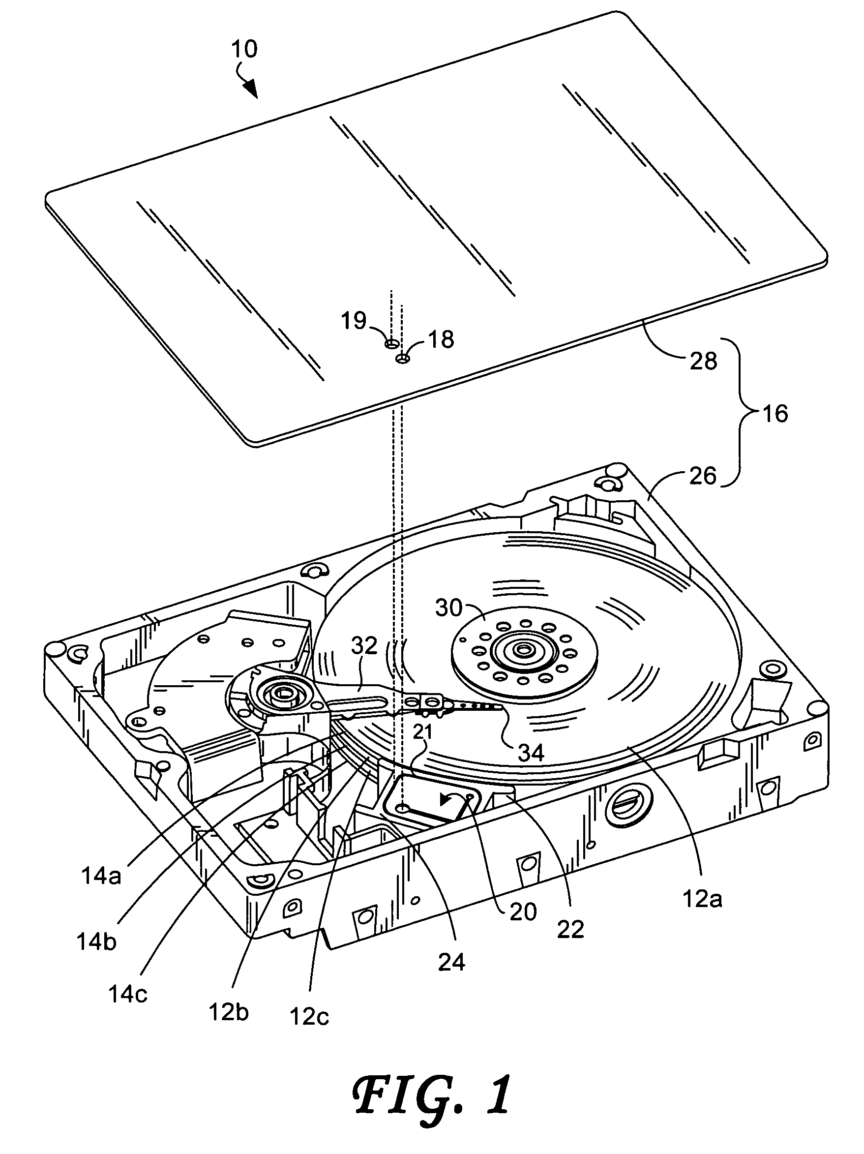
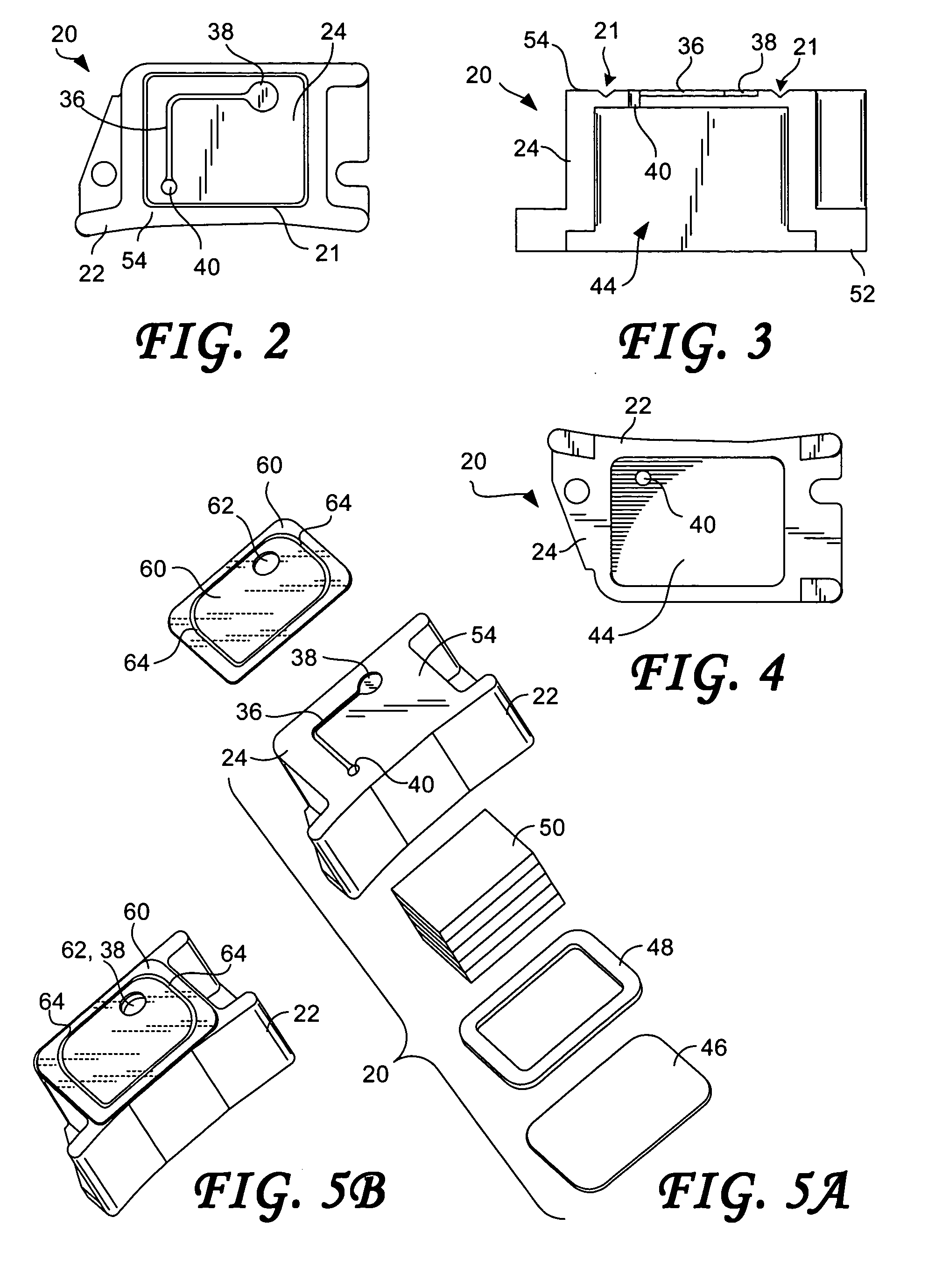
[0027]The drawings illustrate aspects of a disk drive and sub-components thereof, according to embodiments of the present invention. FIG. 1 shows a disk drive 10 constructed in accordance with an embodiment of the present invention. The disk drive 10 includes at least one rotatable disk 12 (individually denoted 12a-c). The disks 12a-c respectively include disk edges 14a-c. The disk drive 10 further includes a disk drive housing 16 having a breather hole 18 formed through the disk drive housing 16. The disk drive 10 further includes a breather filter 20 in mechanical communication with the disk drive housing 16. The breather filter 20 may include a shroud portion 22 positioned adjacent the disk edges 14a-c. The shroud portion 22 may be formed to extend along the disk edges 14a-c for mitigating airflow adjacent the disks 12a-c. The breather filter 20 further includes a breather filter housing portion 24 integrated with the shroud portion 22. The breather filter housing portion 24 is d...


PUM

PropertyMeasurementUnit
forceaaaaaaaaaa
humidityaaaaaaaaaa
roughnessaaaaaaaaaa

Abstract

A disk drive includes a disk drive housing having a breather hole and a separate leak testing hole, both the breather hole and the leak testing hole being formed through the disk drive housing, and a drive sub-component attached to a surface of the disk drive housing so as to form an interface between the sub-component and the surface of the housing. The interface defines an interface outer perimeter and a sealed airflow testing channel in fluid communication only with the leak testing hole to enable a non-destructive detection of leaks at the interface. The airflow testing channel may be disposed within the interface outer perimeter.

Description

BACKGROUND OF THE INVENTION[0001]1. Field of the Invention[0002]The present invention relates to disk drives. More particularly, the present invention relates to breather filters and to leak testing drives equipped with such breather filters.[0003]2. Description of the Prior Art[0004]The typical hard disk drive includes a head disk assembly (HDA) and a printed circuit board assembly (PCBA) attached to a disk drive base of the HDA. The head disk assembly includes at least one magnetic disk, a spindle motor for rotating the disk, and a head stack assembly (HSA) having an actuator assembly having at least one transducer head, typically several, for reading and writing data from the disk. The printed circuit board assembly includes a servo control system in the form of a disk controller for generating servo control signals. The head stack assembly is controllably positioned in response to the generated servo control signals from the disk controller. In so doing, the attached heads are m...

Claims


Application Information

Patent Timeline
Patent Type & Authority Patents(United States)
IPC IPC(8): G11B33/14
CPCG11B25/043G11B33/1486
Inventor CHOY, MICHAEL G.GUSTAFSON, JOHN R.ROBINSON, PETER G.
Owner WESTERN DIGITAL TECH INC
Why Eureka
Try Eureka