System and method for providing destination-to-source protection switch setup in optical network topologies

a protection switch and optical network topology technology, applied in the field of network communication systems, can solve the problems of unforeseeably immense bandwidth demand, inability to increase the bandwidth, and inability to quickly recover, and achieve the effect of efficient establishing protection routes

Inactive Publication Date: 2007-09-25
SCHOFIELD TECH
View PDF8 Cites 86 Cited by
  • Summary
  • Abstract
  • Description
  • Claims
  • Application Information

AI Technical Summary

Benefits of technology

[0012]The present invention is directed to a system and method for efficiently establishing protection routes in networks, more particularly in WDM optical mesh networks. The invention provides a new protection protocol that utilizes a destination-to-source communication channel to establish the source-to-destination protection route. The communication channel is established from the node that detected the failed link back towards a transmitting node on the opposite side of the failed link. The node detecting the failure can be any one of nodes after the failed link, including the final destination node. Similarly, the transmitting or source node can be any one of the nodes before the failed link, including the source node at which the information transfer was origina...

Problems solved by technology

Essentially, this has been due to the failure to multiplex signals on a given fiber.
In this mode, service providers quickly experience fiber exhaustion such that bandwidth can no longer be increased unless more fibers are installed.
This additional bandwidth, while beneficial, was very quickly dev...

Method used


Image

  • System and method for providing destination-to-source protection switch setup in optical network topologies
  • System and method for providing destination-to-source protection switch setup in optical network topologies
  • System and method for providing destination-to-source protection switch setup in optical network topologies

Examples


Embodiment Construction

[0025]In the following description of the various embodiments, reference is made to the accompanying drawings which form a part hereof, and in which is shown by way of illustration various embodiments in which the invention may be practiced. It is to be understood that other embodiments may be utilized, and structural and functional modifications may be made without departing from the scope of the present invention.

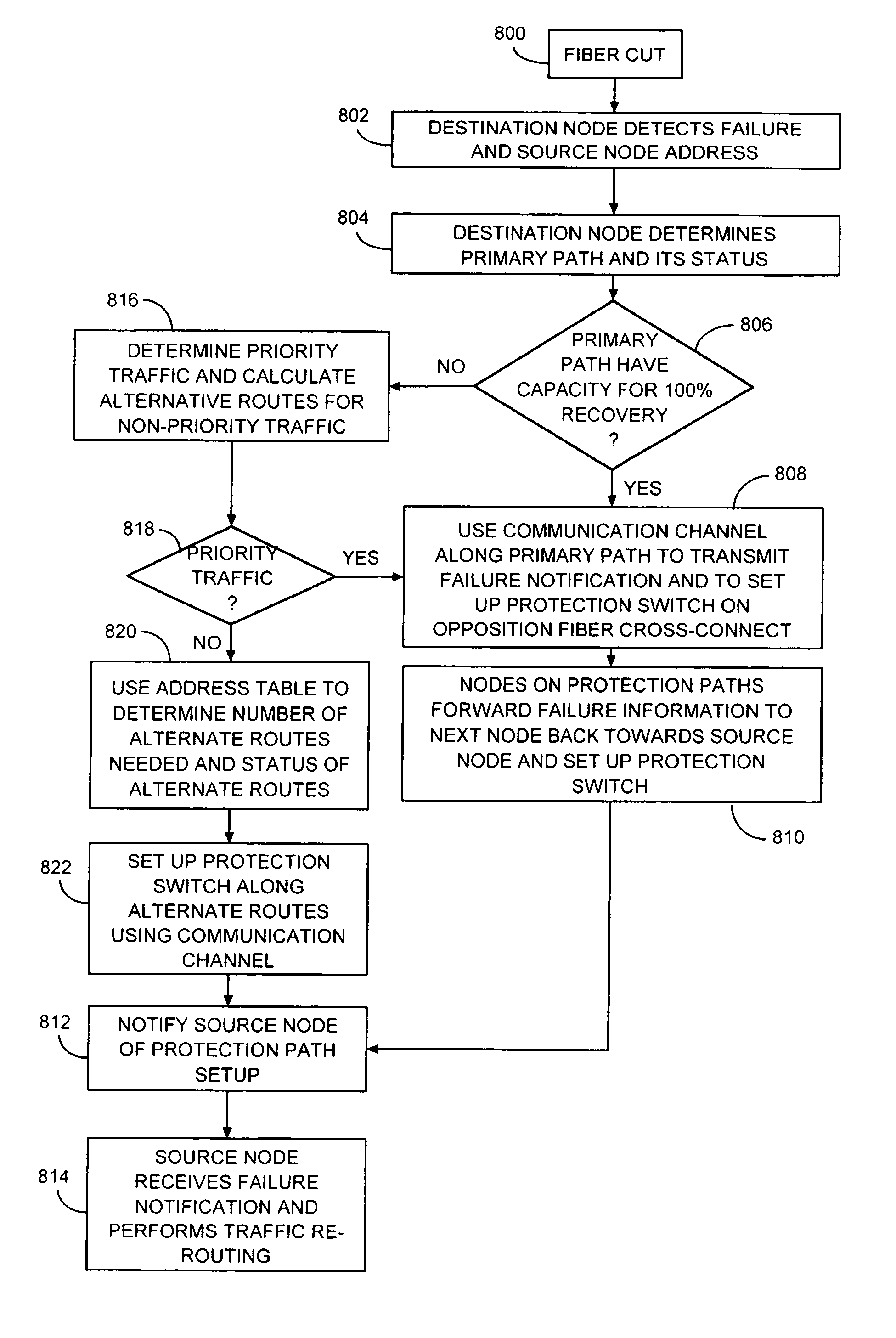
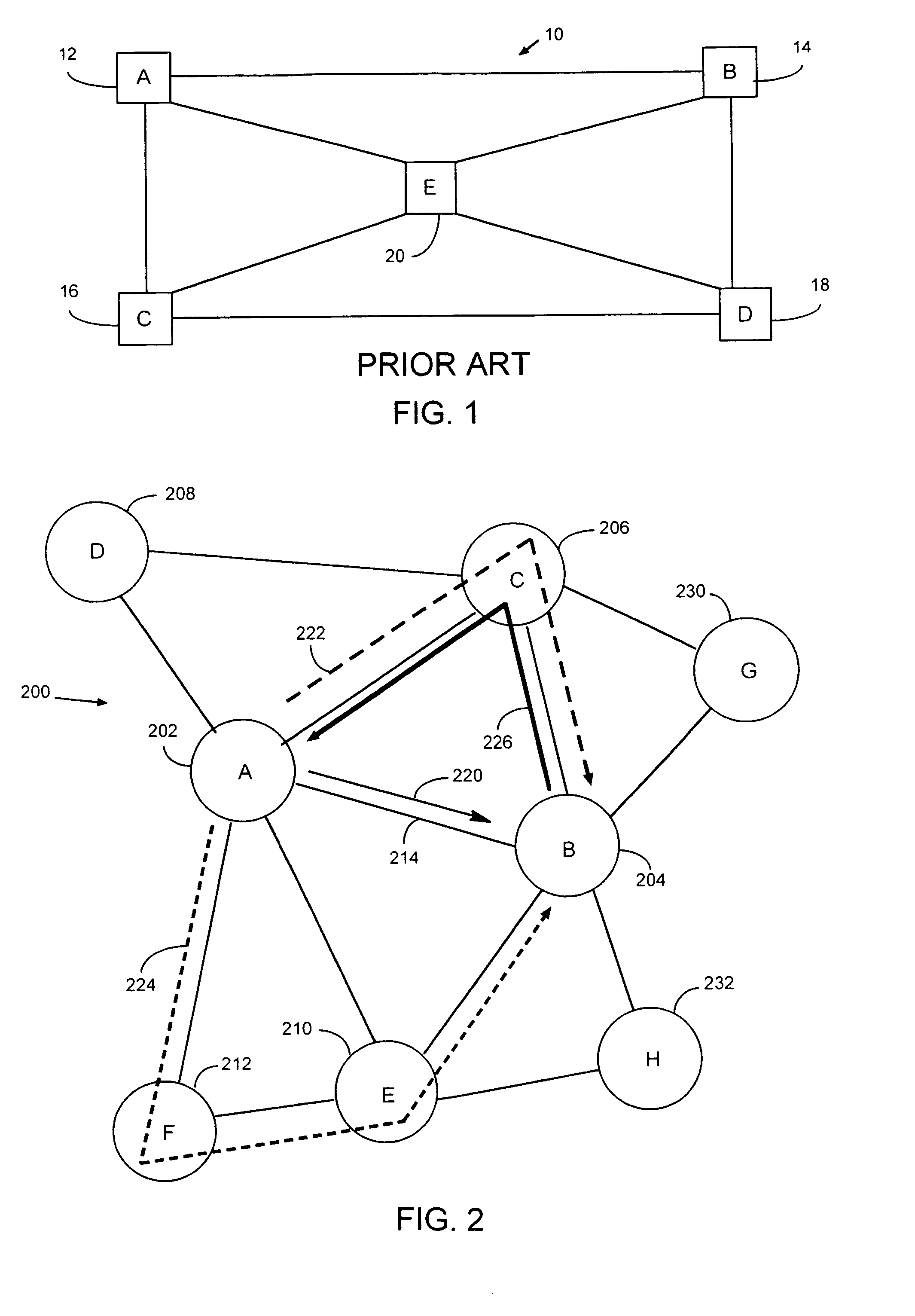
[0026]The present invention is generally directed to a system and method for efficiently establishing protection routes in mesh network topologies, and more particularly in WDM mesh networks. The invention includes a new protection protocol that uses a communication channel to set up the protection route from the node detecting the failure back towards the transmitting node of the failed link. The node detecting the failure can be any one of nodes after the failed link, including the final destination node. Similarly, the transmitting or source node can be any one of the ...


PUM


Abstract

A system and method for establishing protection routes in optical mesh networks. A protection protocol is provided that utilizes a destination-to-source communication channel to establish a source-to-destination protection route. The communication channel is established from the node detecting the failed link back towards the transmitting node. As the destination-to-source communication channel is being established back towards the source node, it concurrently directs the nodes along this path to perform switching functions to subsequently allow the information originally intended for transmission via the failed link to be switched to the alternate protection path. Various manners of ascertaining the protection routes are also provided, including predetermined and/or dynamically-generated protection paths established via the destination-to-source communication channel.

Description

FIELD OF THE INVENTION[0001]The present invention relates generally to network communications systems, and more particularly, to a method and apparatus for establishing protection paths in optical networks from destination node to source node, to immediately avail alternate paths to source nodes of failed links upon the source node's notification of the link failure.BACKGROUND OF THE INVENTION[0002]The modern communications era has brought about a tremendous proliferation of wireline and wireless networks. Computer networks, television networks, and telephony networks in particular are experiencing an unprecedented technological expansion, fueled by consumer demand. The ever-increasing need for bandwidth has exceeded even the most perspicacious expectations, as the explosion of data and multimedia transmissions are breaking the seams of the networking infrastructure. This has propelled an intense effort to quickly increase the available communications bandwidth.[0003]In line with th...

Claims


Application Information

Patent Timeline
IPC IPC(8): H04B10/00
CPCH04B10/032H04J14/0268H04J14/0269H04J14/0284
Inventor PAN, JIN-YI
Owner SCHOFIELD TECH
Why Eureka
Try Eureka