Utility lamp

a technology for lamps and lampshades, applied in the field ofutility lamps, can solve the problems of low conversion efficiency of electrical power to light, difficult to produce in high volume with low cost for the mass market, and relatively short li

Inactive Publication Date: 2007-10-02
KELLY WILLIAM M
View PDF8 Cites 97 Cited by
  • Summary
  • Abstract
  • Description
  • Claims
  • Application Information

AI Technical Summary

Problems solved by technology

However, these suffer from having a relatively short life, some hundreds of hours, and so frequent replacement is necessary.
In addition, the conversion efficiency from electrical power to light is not very good, especially for incandescent sources.
It appears that these approaches all suffer from being complex and thus difficult to produce in high volumes with low cost for the mass market.

Method used


Image

  • Utility lamp
  • Utility lamp
  • Utility lamp

Examples


Embodiment Construction

Brief Description of the Drawings

[0031]The invention will be more clearly understood from the following description of some embodiments thereof, given by way of example only with reference to the accompanying drawings in which:

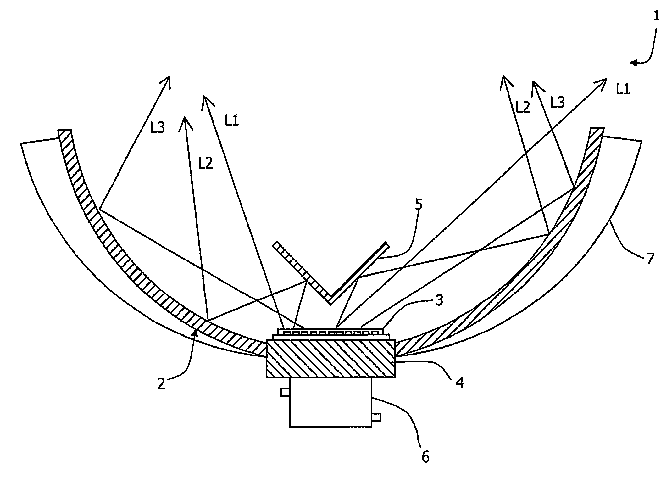
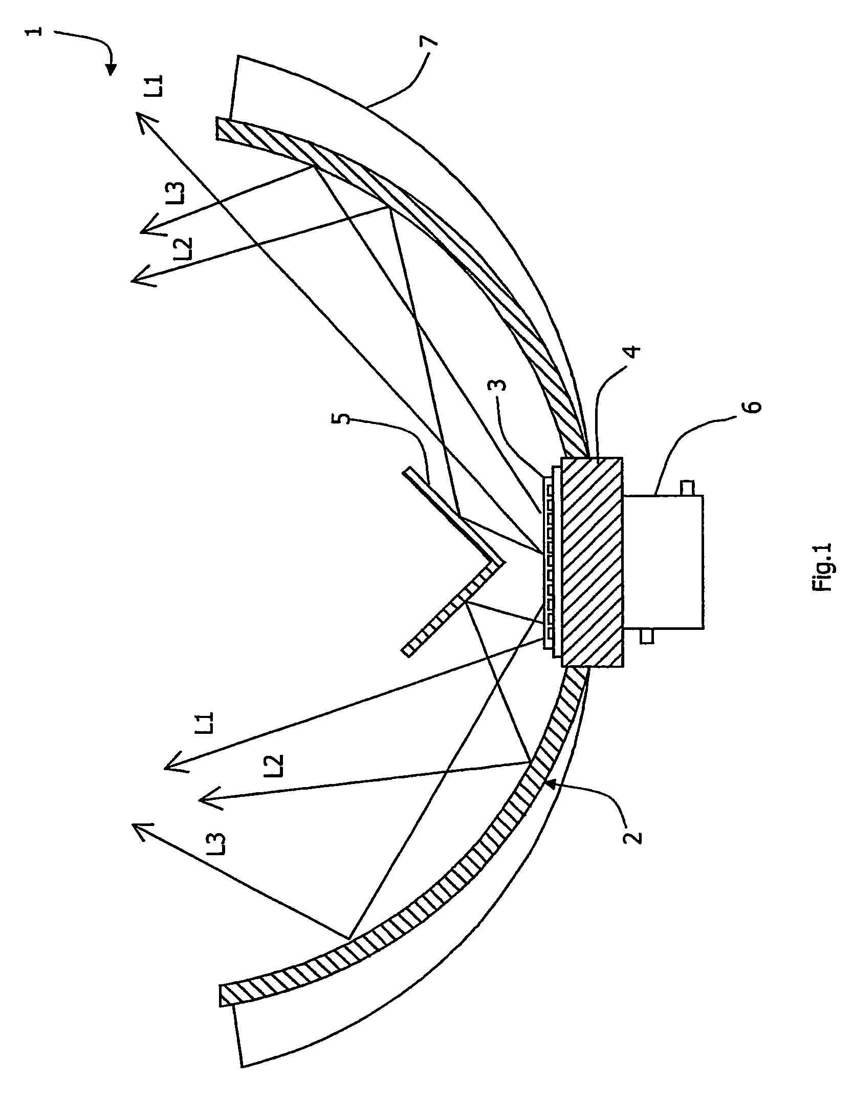
[0032]FIG. 1 is a diagrammatic cross-sectional sketch of a utility lamp of the invention;

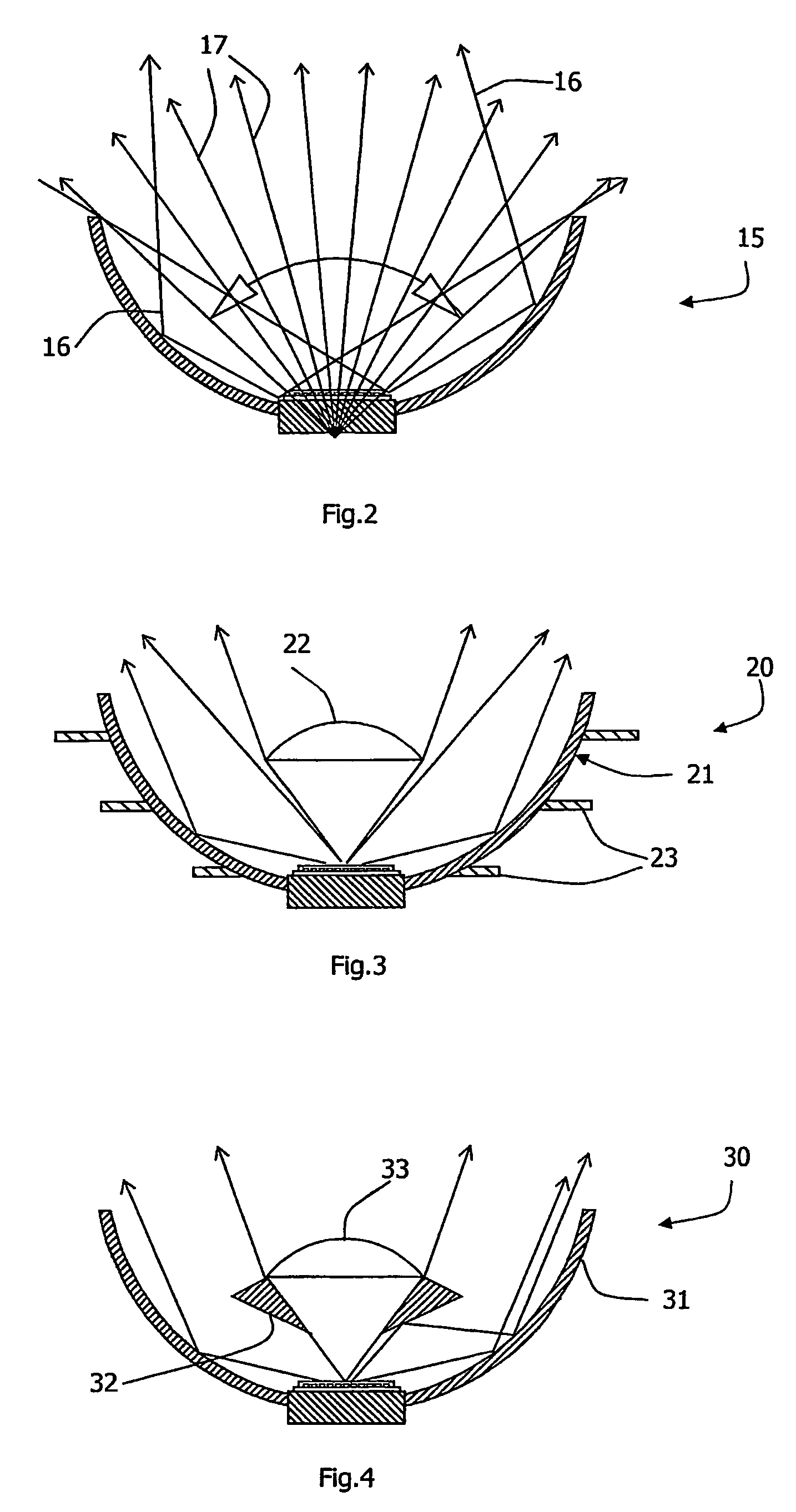
[0033]FIGS. 2 to 4 are cross-sectional sketches of alternative utility lamps of the invention; and

[0034]FIG. 5 is a more detailed diagram showing mounting of LEDs on a substrate in thermal contact with the lamp's reflector;

[0035]FIG. 6 is a plan view showing the arrangement of LEDs in another embodiment;

[0036]FIG. 7 is a diagrammatic cross-sectional view of a simple lamp, having only one LED;

[0037]FIG. 8 is a diagrammatic cross-sectional view of a further lamp; and

[0038]FIG. 9 is a diagrammatic cross-sectional view of a lamp of the invention having a reflector with an elevated base for LED support.

DESCRIPTION OF THE EMBODIMENTS

[0039]Referring to FIG. 1 a utility lamp 1 com...


PUM


Abstract

A utility lamp (1) comprises a curved reflector (2) having a spherically curved surface. An array of LEDs (3) is arranged in an electrical circuit on a thin substrate mounted via thermally conductive epoxy on a thermally-conductive base (4), which in turn forms an integral part of the reflector (2). The LEDs are mounted for efficient heat transfer by conduction to the reflector (2). The reflector (2) thus operates as both a light reflector and as a radiative heat sink. The heat radiating properties of the reflector are enhanced by integral fins (7) extending in the radial direction around the periphery of the reflector (2). The reflector (2) is of integral aluminium construction.

Description

[0001]This is a continuation of PCT / IE2005 / 000015 filed 17 Feb. 2005 and published in English.INTRODUCTION[0002]1. Field of the Invention[0003]The invention relates to a utility lamp of the type for a wide range of uses such as illuminating shop windows or general domestic use.[0004]2. Prior Art Discussion[0005]At present, most such lamps have as a light source a fluorescent tube or an incandescent bulb. However, these suffer from having a relatively short life, some hundreds of hours, and so frequent replacement is necessary. In addition, the conversion efficiency from electrical power to light is not very good, especially for incandescent sources. It has been proposed in patent literature to use light emitting diodes (LEDs) instead as the light source, since LEDs have lifetimes of more than 100,000 hours provided the operating temperature of the LEDs is kept within the required limits, and have good operating efficiencies. U.S. Pat. No. 6,367,949 describes an approach in which a h...

Claims


Application Information

Patent Timeline
Patent Type & Authority Patents(United States)
IPC IPC(8): F21V7/20F21K99/00F21V7/00F21V13/04F21V21/00F21V29/00F21V29/505H01L33/00
CPCF21K9/137F21V29/773F21S48/328F21V29/004F21V29/505F21V29/767F21L14/023F21V7/0008F21V7/0025F21V13/04F21V19/001F21Y2101/02F21V5/048F21Y2111/002F21Y2111/007Y10S362/80F21K9/233F21Y2107/10F21Y2107/40F21Y2115/10F21V5/10F21V29/70F21V29/74F21V29/777
Inventor KELLY, WILLIAM M
Owner KELLY WILLIAM M
Why Eureka
Try Eureka