
Compensation of flight path deviation for spotlight SAR

Active Publication Date: 2007-10-02
RAYTHEON CO
View PDF18 Cites 28 Cited by
  • Summary
  • Abstract
  • Description
  • Claims
  • Application Information

AI Technical Summary

Benefits of technology

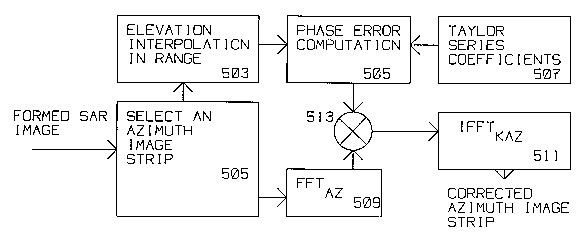
[0013]Phase error compensation and compensation in azimuth (spacial frequency) is computed using the Taylor series coefficients, a Fast Fourier Transform and an inverse Fast Fourier Transform for the first strip to obtain first strip corrected data and for the adjacent strip to obtain second st

Problems solved by technology

However, the actual path may diverge from the ideal path by rising or dipping below the reference plane and not maintaining rectilinear direction.

Method used


Image

  • Compensation of flight path deviation for spotlight SAR
  • Compensation of flight path deviation for spotlight SAR
  • Compensation of flight path deviation for spotlight SAR

Examples


Embodiment Construction

[0022]In the present disclosure, a SAR image is formed from a sequence of pulses transmitted and reflected from static objects within an area of interest. Received data in a pulse interval is comprised of range samples. The range samples have a fast rate. Conversely, the pulse repetition rate has a slow rate. Both the fast rate and the slow rate are used as inputs for image formation processing.

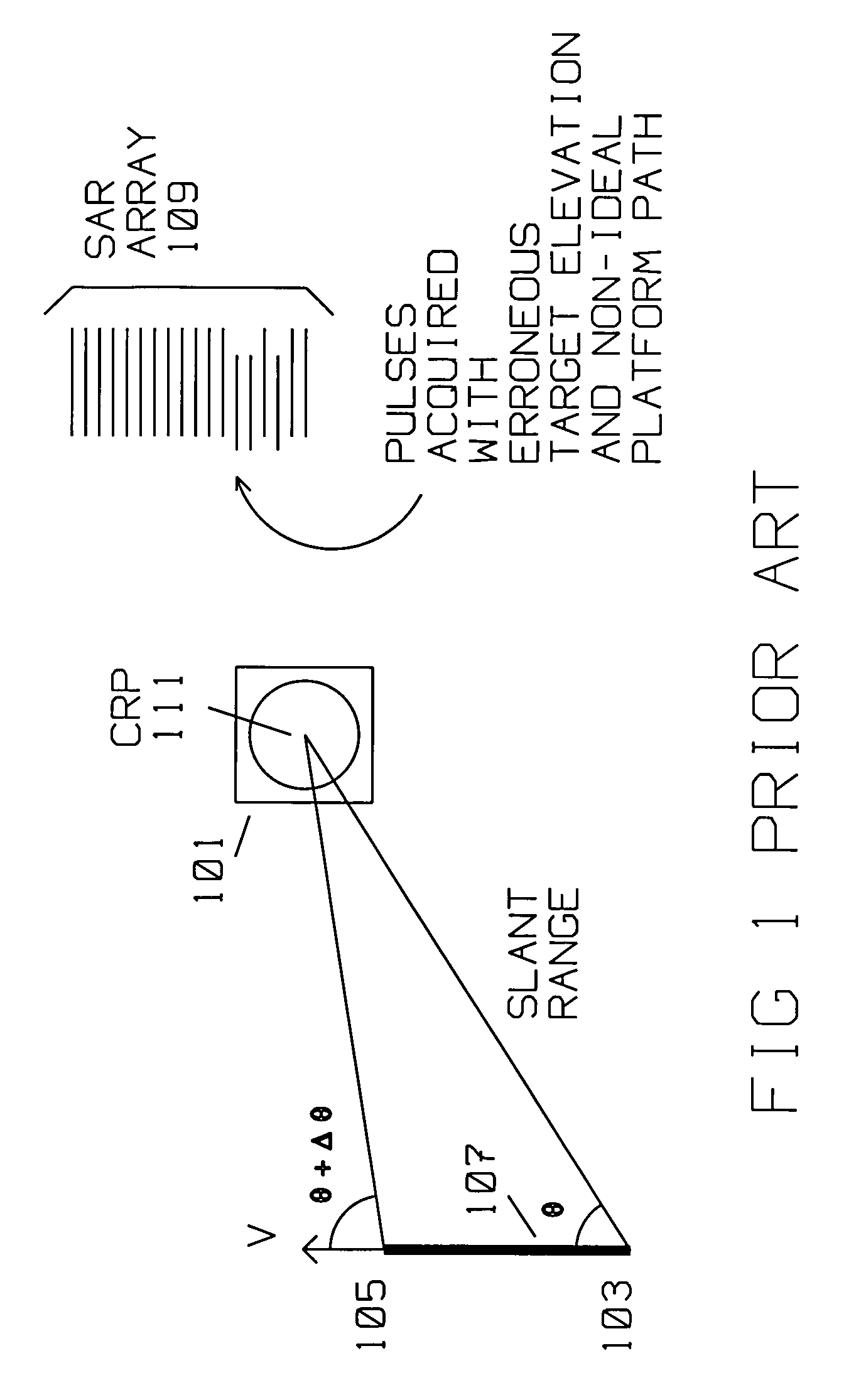
[0023]FIG. 1 shows the typical prior art geometric relationship between a moving platform carrying a radar transmitter / receiver using Synthetic Aperture (SAR) spot search methods imaging patch 101 by said radar transmitter / receiver. The moving platform is initially at position 103, travels along a rectilinear path 107 with velocity V to position 105. In SAR spot mode applicable in this description, the SAR antenna azimuth is variable at azimuth angle θ to θ+Δθ oriented towards patch 101 as the platform moves with velocity V. The moving platform moves from position 103 to position 105 along pa...


PUM


Abstract

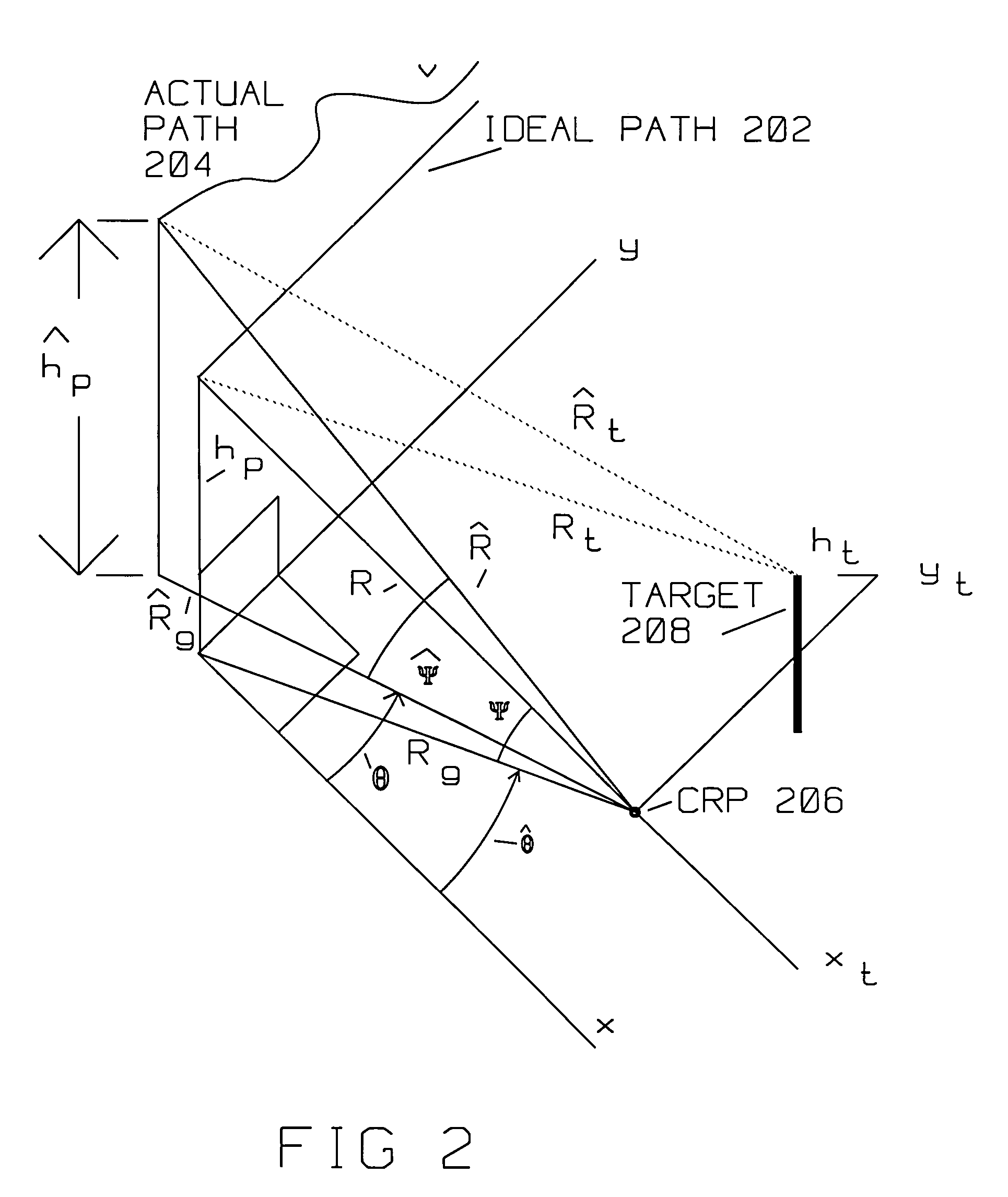
A radar acquires a formed SAR image of radar scatterers in an area around a central reference point (CRP). Target(s) are within the area illuminated by the radar. The area covers terrain having a plurality of elevations. The radar is on a moving platform, where the moving platform is moving along an actual path. The actual path is displaced from an ideal SAR image acquisition path. The radar has a computer that divides the digital returns descriptive of the formed SAR image into multiple blocks, such as a first strip and an adjacent strip. The first strip is conveniently chosen, likely to generally align with a part of the area, at a first elevation. An adjacent strip covers a second part of the area at a second elevation. The first strip is overlapping the adjacent strip over an overlap portion. The first and second elevation are extracted from a terrain elevation database (DTED). Horizontal displacement of returns (range deviation) is computed for each strip using the elevation information from the terrain elevation database. Taylor series coefficients are computed for the horizontal displacement due to terrain elevation using the ideal path, the actual path and central reference point. Actual flight path deviation is available at each pulse position while azimuth frequency is given in azimuth angle off mid angle point. Remapping between indices in two arrays is also computed. Phase error compensation and compensation in azimuth (spacial frequency) is computed using the Taylor series coefficients, a Fast Fourier Transform and an inverse Fast Fourier Transform for each strip. Phase error compensation is applied to the digital returns from each strip to obtain the SAR image. The SAR image is further improved by having the first strip corrected data and the second strip corrected data merged over the overlap portion to generate a relatively seamless SAR image.

Description

[0001]This invention was made with Government support under Contract No. F19628-00-C-0100 awarded by the Department of the Air Force. The Government has certain rights in this invention.BACKGROUND OF THE INVENTION[0002]1. Field of Invention[0003]This invention is in the field of Synthetic Aperture Radar (SAR) where the platform acquiring the image deviates from an ideal flight path and the terrain being illuminated has variations in elevation above sea level.[0004]2. Description of the Related Art[0005]Synthetic Aperture Radar (SAR) is used for ground mapping as well as target identification. The general principle behind SAR is to coherently combine the amplitude and phase information of radar returns from a plurality of sequentially transmitted pulses. These pulses are from a relatively small antenna on a moving platform. As the platform moves, the information contained in the pulses is coherently combined to arrive at a high resolution SAR image.[0006]The plurality of returns crea...

Claims


Application Information

Patent Timeline
IPC IPC(8): G01S13/90G01S13/00
CPCG01S7/00G01S13/9035G01S7/40G01S2013/9052G01S13/9052G01S13/9019
Inventor CHO, KWANG M.HUI, LEO H.
Owner RAYTHEON CO
Learn More