Heat dissipation device having a dual-fan arrangement

a heat dissipation device and fan arrangement technology, which is applied in the direction of electrical apparatus construction details, instruments, and semiconductor/solid-state device details, can solve the problems of poor heat dissipation efficiency of the fins, inability to quickly and effectively expel heated air from the bottom of the fins, and affecting the stability of the operation of the electronic devices, so as to quickly and efficiently remove the heat sink

Inactive Publication Date: 2007-10-02
HON HAI PRECISION IND CO LTD +1
View PDF10 Cites 69 Cited by
  • Summary
  • Abstract
  • Description
  • Claims
  • Application Information

AI Technical Summary

Benefits of technology

[0005]A heat dissipation device in accordance with a preferred embodiment of the present invention comprises a heat sink, a first fan disposed on one part of the heat sink, a second fan disposed on another part of the heat sink and a cover disposed to enclose the heat sink, the first fan and the second fan. The second fan helps the airflow produced by the first fan flowing to the heat sink to quickly leave the heat sink so that heat absorbed by the heat sink from a heat-generating electronic component can be quickly and efficiently taken away. The cover defines communicable first and second rooms. The first fan is received in the first room, while the second fan is received in the second room.

Problems solved by technology

If the heat is not dissipated duly, the stability of the operation of the electronic devices will be impacted severely.
The heated air cannot be quickly and effectively expelled from the bottom of the fins.
Thus, heat dissipation efficiency of the fins is poor and the heat transfer efficiency between the base and the bottom of the fins is low.
Heat accumulated at bottom of the fins of the heat sink of the periphery card is particularly serious, which requires an immediate solution.

Method used


Image

  • Heat dissipation device having a dual-fan arrangement
  • Heat dissipation device having a dual-fan arrangement
  • Heat dissipation device having a dual-fan arrangement

Examples


Embodiment Construction

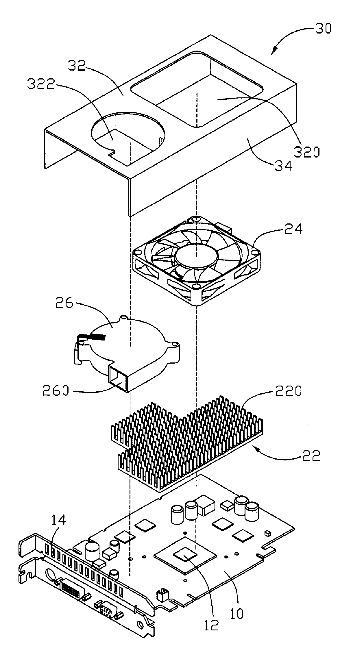
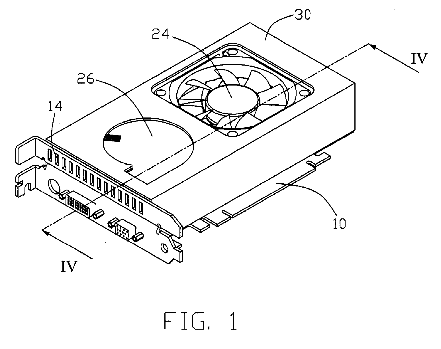
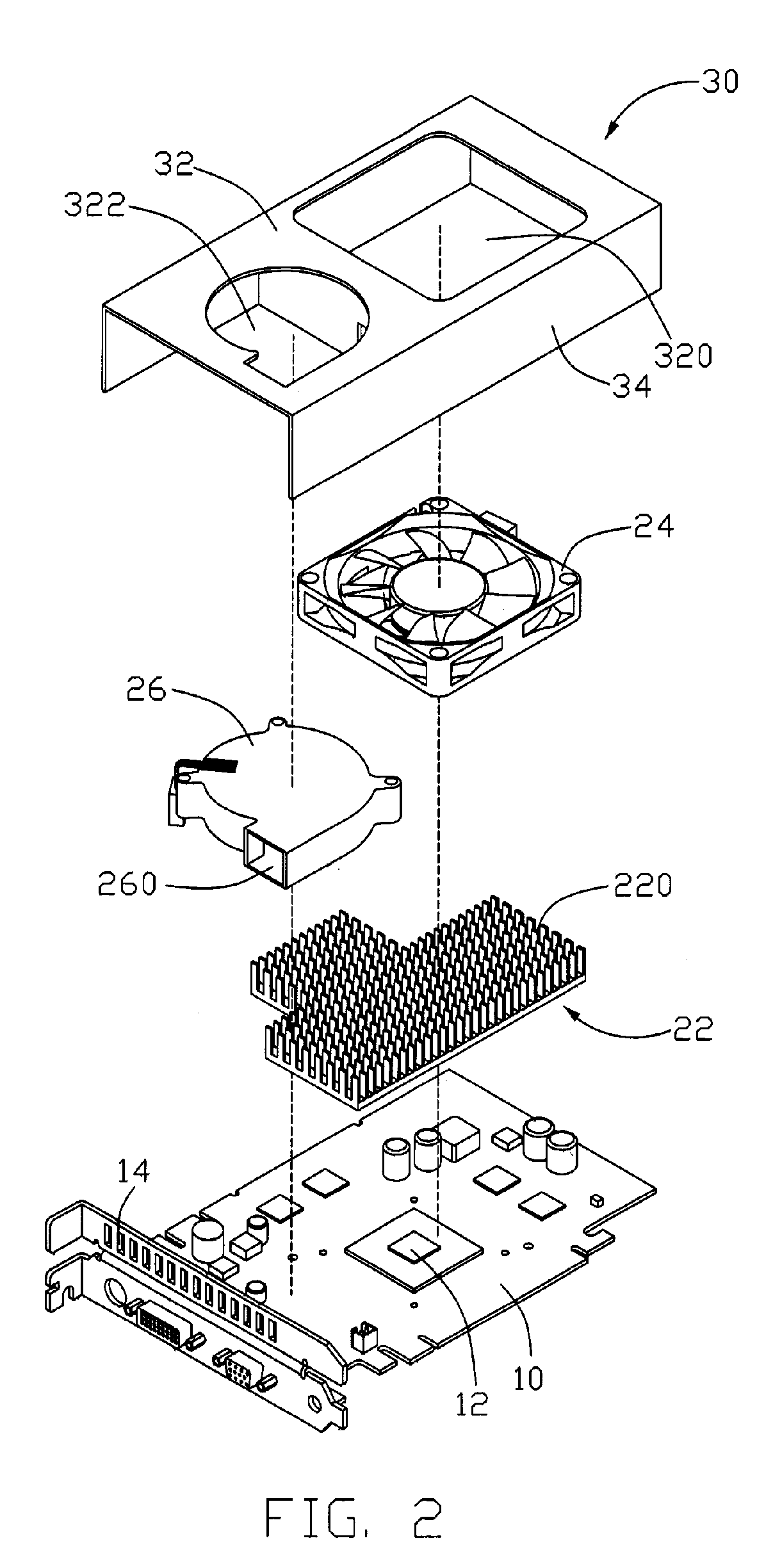
[0011]FIG. 1 shows a heat dissipation device in accordance with a preferred embodiment of the present invention, mounted on a printed circuit board 10 of a VGA card. The printed circuit board 10 has a heat-generating electronic component 12 (FIG. 2) attached thereon, which is a graphic processing unit (GPU) in this embodiment.

[0012]Also referring to FIGS. 2-3, the heat dissipation device comprises a heat sink 22, a first fan 24, a second fan 26 and a cover 30. The heat sink 22 has a bottom base (not labeled) contacting with the heat-generating electronic component 12 to receive heat generated by the heat-generating electronic component 12. A plurality of fins 220 is extended upwardly from the base to dissipate the heat on the base to ambient air. The first fan 24, which is an axial fan, is disposed on a top of the fins 220 of the heat sink 22 and produces an airflow to directly flow from the top of the fins 220 to a bottom of the fins 220 of the heat sink 22. The second fan 26, whic...


PUM


Abstract

A heat dissipation device includes a heat sink (22), a first fan (24) disposed on one part of the heat sink, a second fan (26) disposed on another part of the heat sink and a cover (30) disposed to enclose the heat sink, the first fan and the second fan. The second fan draws the air produced by the first fan and flowing through the heat sink to quickly leave the heat sink.

Description

FIELD OF THE INVENTION[0001]The present invention generally relates to a heat dissipation device for removing heat from an electronic component, and particularly to a heat dissipation device comprising double fans to enhance an airflow flowing through a heat sink in contact with the electronic component, which is mounted on a periphery card.DESCRIPTION OF RELATED ART[0002]With advancement of computer technology, electronic devices operate with high speeds. It is well known that the more rapidly the electronic devices operate, the more heat they generate. If the heat is not dissipated duly, the stability of the operation of the electronic devices will be impacted severely.[0003]Generally, in order to ensure the electronic device to run normally, a heat dissipation device is used to dissipate the heat generated by the electronic device. A conventional heat dissipation device includes a heat sink and a fan attached on a top of the heat sink. The heat sink includes a base contacting a h...

Claims


Application Information

Patent Timeline
Patent Type & Authority Patents(United States)
IPC IPC(8): H05K7/20
CPCG06F1/20H01L23/467H01L2924/0002H01L2924/00
Inventor PENG, XUE-WEN
Owner HON HAI PRECISION IND CO LTD
Why Eureka
Try Eureka