Clean release magnet and the manufacturing method thereof

a technology of clean release magnet and manufacturing method, applied in the field of labels, can solve the problems of contaminating the product contents, limiting the use potential of magnetic labels, and damaging the product labels themselves

Active Publication Date: 2007-10-09
RAYPRESS CORP
View PDF23 Cites 7 Cited by
  • Summary
  • Abstract
  • Description
  • Claims
  • Application Information

AI Technical Summary

Benefits of technology

[0010]The invention solves the problems and overcomes the drawbacks and disadvantages of the prior art by providing a magnetic label, which may be adhered to and removed from a product without damaging the product label itself.

Problems solved by technology

Thus far, the usage potential of magnetic labels has been limited, in that the magnetic label typically requires a separate means of delivery to a customer than the advertised product itself.
Moreover, if the magnetic label is affixed to an advertised product, removal of the label from the product in turn damages the product label itself, or may contaminate the product contents.
The conventional manufacturing methods of the past have had limited potential, in that once the magnetic labels have been cut, a seller generally has to separately distribute the magnetic label with each product.
For products manufactured by the thousands or millions, such distribution requirements can significantly increase the overall cost of the product.
These conventional magnetic labels however have several of the same disadvantages and drawbacks of the conventional magnetic labels, as described above.
Some of the key drawbacks generally include the limited usage potential, wherein the seller is required to deliver the labels separately with each product, or wherein removal of the label from a product damages the product label itself.
Likewise, from a manufacturing standpoint, the labels described in the above-identified U.S. Patents also do not facilitate or reduce the cost of manufacturing and distribution of products with the labels.

Method used


Image

  • Clean release magnet and the manufacturing method thereof
  • Clean release magnet and the manufacturing method thereof
  • Clean release magnet and the manufacturing method thereof

Examples


Embodiment Construction

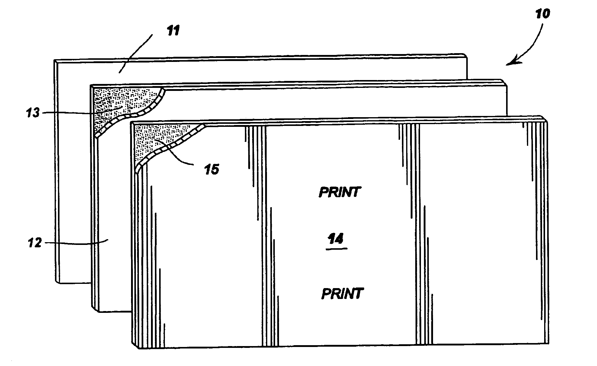
[0026]As shown in FIG. 1, a clean release magnet according to the present invention, generally designated 10, may include a clear pressure sensitive carrier layer 11 having a permanent adhesive (not shown) applied to the back surface thereof so as to enable permanent affixation of clean release magnet 10 onto any type of product or item. Clear pressure sensitive carrier layer 11 may alternatively have a clean release adhesive (not shown) applied to its back surface, instead of the permanent adhesive.

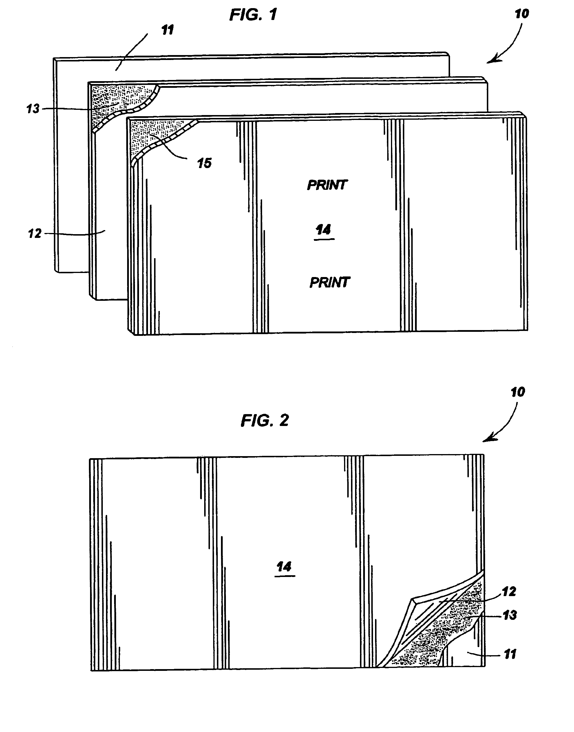
[0027]As shown in FIG. 2, a flexible magnet 12 may be affixed to the clear pressure sensitive carrier layer 11 with a clean release adhesive 13. Clean release adhesive 13 allows flexible magnet 12 to be peeled off or removed from clear pressure sensitive carrier layer 11, without leaving a tacky or sticky residue on flexible magnet 12 or on the exposed surface of clear pressure sensitive carrier layer 11. Although layer 11 has been denoted as a clear pressure sensitive carrier layer, it ...


PUM

PropertyMeasurementUnit
pressure sensitiveaaaaaaaaaa
depthaaaaaaaaaa
flexibleaaaaaaaaaa

Abstract

The present invention includes a clean release magnet label and manufacturing method thereof. The clean release magnet includes a pressure sensitive carrier layer having a permanent adhesive applied to a first face and a clean release adhesive applied to a second face. A magnet layer is removably affixed to the pressure sensitive carrier layer with the clean release adhesive, and a filmic face layer, having printing thereon, is attached to the magnet layer with an adhesive. The method of manufacturing enables manual or automatic application of clean release magnets onto products. With this arrangement, the magnet layer is non-tacky when removed from the pressure sensitive carrier layer, the original product label is visible upon removal of the clean release magnet and the product contents remain free from contamination from the clean release magnet.

Description

RELATED APPLICATIONS[0001]This application claims benefit of priority of application Ser. No. 10 / 180,084, filed Jun. 27, 2002.BACKGROUND OF INVENTION[0002]a. Field of Invention[0003]The invention relates generally a label and a manufacturing method thereof, and, more particularly to a label that is a clean release magnet, and a manufacturing method thereof.[0004]b. Description of Related Art[0005]A need exists for an improved label, having a magnet attached thereto, which may be efficiently and economically manufactured, and which may be adhered to a product and removed therefrom without damaging the product or obstructing the product label itself.[0006]Magnetic labels are well known in the art and generally include advertising material printed on one side of label stock and a magnet permanently adhered to the other side. In use, magnetic labels are generally placed onto a metallic object and may serve the dual purpose of advertising a product, and securing paper and other such mate...

Claims


Application Information

Patent Timeline
Patent Type & Authority Patents(United States)
IPC IPC(8): G09F3/10B32B7/06G09F3/02G09F7/04
CPCB32B7/06G09F7/04G09F3/0292G09F3/10G09F3/02B32B2307/208B32B2519/00
Inventor RAY, III, THOMAS D.MULLALY, MARKGILL, THOMMY W.MARTIN, RANDALL D.ALDEN, ROBERT J.
Owner RAYPRESS CORP
Why Eureka
Try Eureka