Helium process cycle

a process cycle and helium technology, applied in the field of helium process cycle, can solve the problems of limited effect on maintaining high plant efficiency, reducing plant production, and traditional helium process cycle design and equipment do not always provide the ability to reduce refrigeration and liquefaction production, etc., and achieve the effect of high operating efficiency

Active Publication Date: 2007-10-09
JEFFERSON SCI ASSOCS LLC
View PDF12 Cites 16 Cited by
  • Summary
  • Abstract
  • Description
  • Claims
  • Application Information

AI Technical Summary

Benefits of technology

[0005]It is therefore an object of the present invention to provide a helium process cycle and apparatus that while allowing for designed and reduced production and / or refrigeration capacity maintains the high operating efficiency of a well designed plant operating at the required capacity.SUMMARY OF THE INVENTION
[0006]According to the present invention there is provided an improved process cycle and apparatus for the implementation thereof comprising: a warm recycle compressor set, a warm consumer load return compressor, high pressure gas storage, a warm end pre-cooler stage and a cold end cooler stage. High pressure gas delivered by the warm recycle compressor set is cooled by the warm end pre-cooler and cold end cooler. The cold end cooler subdivides the high pressure flow to the recycle sub-cooler and the consumer load sub-cooler. Flow from the recycle sub-cooler is combined with the recycle return flow in the cold end cooler and warm end pre-cooler, so being warmed returns to the suction of the recycle compressor set. The consumer load return flow is delivered to the consumer load sub-cooler. Flow from the consumer load sub-cooler is warmed passing through the cold end cooler and warm end pre-cooler, returning to the suction of the consumer load compressor. Utilizing the unique gas management valve regulation, the unique process cycle and apparatus design in which the consumer load return flow is separate from the recycle return flow, the pressure ratios of each recycle compressor stage and all main pressures associated with the recycle flow are allowed to vary naturally, thus providing a naturally regulated and balanced floating pressure process cycle that maintains optimal efficiency at design and off-design process cycle capacity and conditions.

Problems solved by technology

Thus, traditional helium process cycle designs and equipment do not always provide the ability to reduce the refrigeration and liquefaction production while maintaining a high operational efficiency.
Although these mechanisms reduce plant production, they have only limited effect on maintaining high plant efficiency.

Method used


Image

  • Helium process cycle
  • Helium process cycle
  • Helium process cycle

Examples


Embodiment Construction

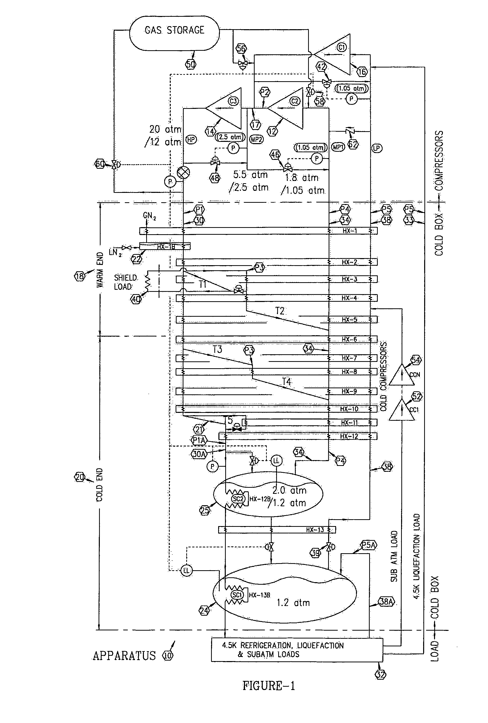
[0010]Referring to FIG. 1 that is a flow schematic of the process cycle of the present invention, the apparatus 10 of the present invention comprises: three warm end compressor sets 12, 14 and 16, a warm end pre-cooler stage 18 and a cold end cooling stage 20. The compressor sets are comprised of a recycle compressor set made up of first and second stage recycle compressor sets 12 and 14 respectively in series and a consumer load return compressor set 16. Consumer load return compressor set 16 delivers an intermediate pressure level gas in between first and second stage recycle compressor sets 12 and 14.

[0011]Warm end pre-cooler 18 comprises a plurality of expansion stages, shown as T1 through T2 in FIG. 1, and may incorporate a liquid nitrogen (LN2) pre-cooler 22. Cold end cooler 20 comprises a plurality of expansion stages, shown as T3 through T4 in FIG. 1, a consumer load expansion stage 21, a recycle sub-cooler 25 and a consumer load sub-cooler 24. It will be readily apparent to...


PUM


Abstract

A unique process cycle and apparatus design separates the consumer (cryogenic) load return flow from most of the recycle return flow of a refrigerator and / or liquefier process cycle. The refrigerator and / or liquefier process recycle return flow is recompressed by a multi-stage compressor set and the consumer load return flow is recompressed by an independent consumer load compressor set that maintains a desirable constant suction pressure using a consumer load bypass control valve and the consumer load return pressure control valve that controls the consumer load compressor's suction pressure. The discharge pressure of this consumer load compressor is thereby allowed to float at the intermediate pressure in between the first and second stage recycle compressor sets. Utilizing the unique gas management valve regulation, the unique process cycle and apparatus design in which the consumer load return flow is separate from the recycle return flow, the pressure ratios of each recycle compressor stage and all main pressures associated with the recycle return flow are allowed to vary naturally, thus providing a naturally regulated and balanced floating pressure process cycle that maintains optimal efficiency at design and off-design process cycle capacity and conditions automatically.

Description

[0001]The United States of America may have certain rights to this invention under Management and Operating Contract No. DE-AC05-84ER 40150 from the Department of Energy.FIELD OF THE INVENTION[0002]The present invention relates to methods and apparatus for the production and refrigeration of a low temperature boiling point gas that maintains high operational efficiency at nominal design and off design operating capacity and conditions using a floating pressure process cycle.BACKGROUND OF THE INVENTION[0003]Traditional cryogenic helium refrigeration and liquefaction process cycles are designed at a specified maximum capacity operating point. In actual practice, however, the consumer load often varies depending upon the refrigeration and / or liquefaction consumer (heat) loads. Thus, traditional helium process cycle designs and equipment do not always provide the ability to reduce the refrigeration and liquefaction production while maintaining a high operational efficiency. During reduc...

Claims


Application Information

Patent Timeline
Patent Type & Authority Patents(United States)
IPC IPC(8): F25J1/00
CPCF25B9/002F25B1/10F25B2400/075
Inventor GANNI, VENKATARAO
Owner JEFFERSON SCI ASSOCS LLC
Why Eureka
Try Eureka