Perforating gun connector

a perforating gun and connector technology, applied in the direction of drilling pipes, mechanical equipment, borehole/well accessories, etc., can solve the problems of significant strength requirements, relatively slow increase assembly process,

Inactive Publication Date: 2007-10-09
SCOTT BRUCE DAVID
View PDF9 Cites 55 Cited by
  • Summary
  • Abstract
  • Description
  • Claims
  • Application Information

AI Technical Summary

Benefits of technology

[0028]An annular seating plane is provided internally of each transition collar to receive an alignment collar secured to each inner loading tube. The inner loading tube is a unitizing element for all of the shaped charges and ignition fuse in a carrier joint. A loading tube collar reference plane contiguously abuts the transition collar seating plane to longitudinally locate the exact position of the detonation booster elements at each end of an inner loading tube. A threaded setting ring or resiliently biased snap-ring secures the tight engagement of the loading tube collar reference plane against the transition collar seating plane, An orientation pin or key secures the correct angular orientation of the inner loading tube with respect to the charge carrier axis.

Problems solved by technology

Although threaded steel carrier connections as previously described are suitably strong for supporting the enormous weight of a steel perforating gun, the incremental assembly process is relatively slow.
Hence, even though CBP technology may reduce the stress demands on a charge carrier connection, significant strength requirements remain.

Method used


Image

  • Perforating gun connector
  • Perforating gun connector
  • Perforating gun connector

Examples


Embodiment Construction

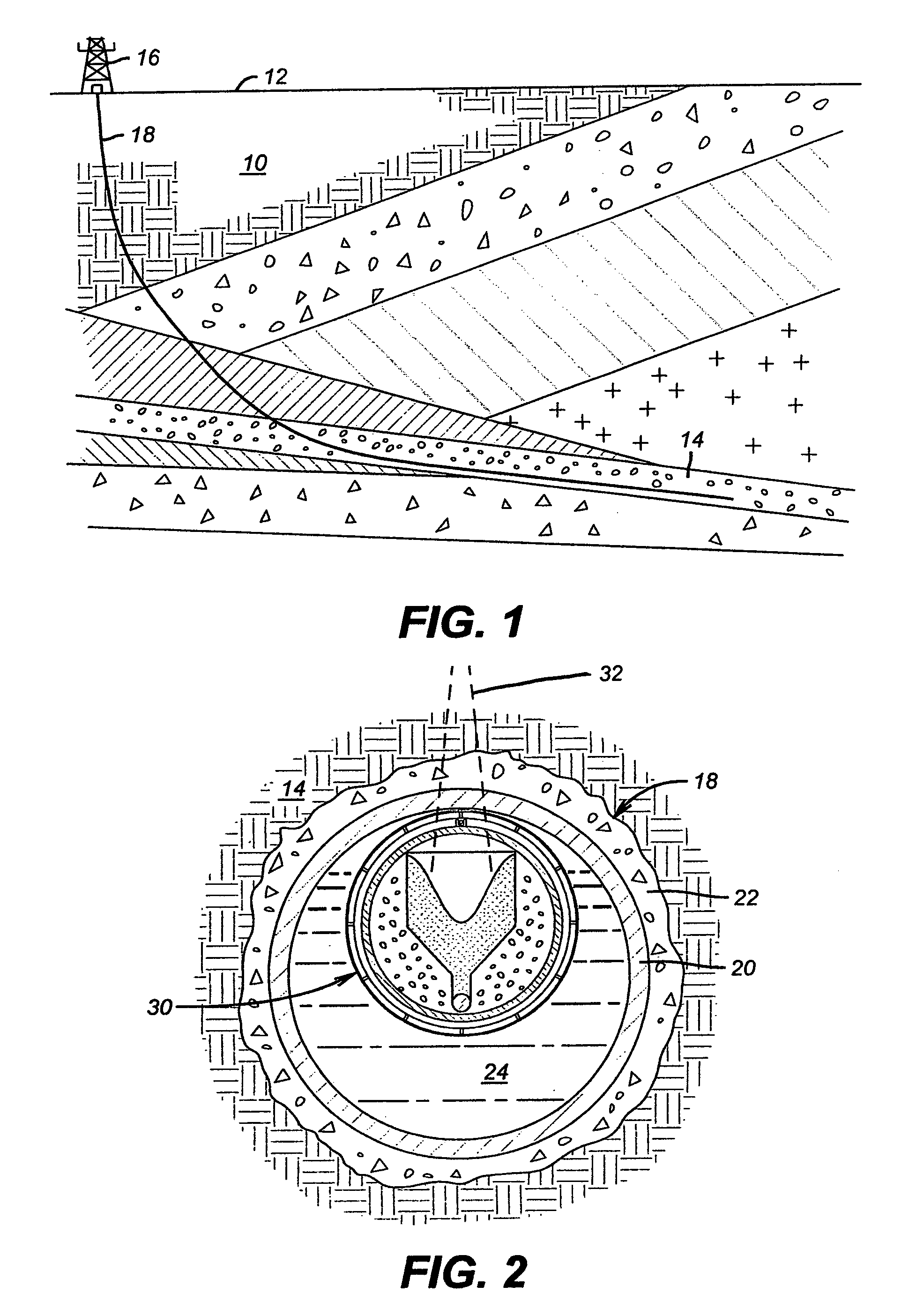
[0059]For environmental reference, FIG. 1 represents a cross-section of the earth 10. Below the earth surface 12, the earth firmament comprises a number of differentially structured layers or strata. For the present purposes, a thin and mildly sloped strata 14 is represented to be of particular interest due to an abundant presence of petroleum.

[0060]From a drilling / production platform 16 on the earth surface 12, an extended wellbore 18 is drilled into and along the strata 14. In this case, the wellbore 18 is drilled to follow the bottom plane of the strata.

[0061]There are many well completion systems. Although the present invention is relevant to all completion systems in one form or another, the “cased hole” completion represented by FIG. 2 serves as a suitable platform for describing the presently preferred embodiments of the invention.

[0062]With respect to FIG. 2, the borehole 18 along the production strata 14 is lined by casing 20 set within a cement sheath 22. In the course of ...


PUM


Abstract

Controlled Buoyancy Perforating technology for highly deviated and substantially horizontal wellbores may include long perforating guns assembled on a rig floor from a multiplicity of light weight and highly engineered shaped charge carrier joints. Tubular housings for such light weight joints may be fabricated from composite materials having steel transition collars. The collars are designed for an angularly coordinated, bayonet assembly and, in most cases, rapid disassembly. The internal volume of each joint is environmentally sealed by a plurality of O-rings. Barbs carried by collet fingers projecting from opposite ends of a sealing sleeve that externally bridges a transition collar union plane secures the union by meshing with detent channels in the respective collars. Individual shaped charge units and cooperative fusing are assembled in a light weight inner loading tube having an alignment collar to secure the angular and axial position of the loading tube relative to the transition collars.

Description

CROSS-REFERENCE TO RELATED APPLICATIONS[0001]Not ApplicableSTATEMENT REGARDING FEDERALLY SPONSORED RESEARCH OR DEVELOPMENT[0002]Not ApplicableBACKGROUND OF THE INVENTION[0003]1. Field of the Invention[0004]This invention generally relates to downhole well tools and specifically to controlled buoyancy perforating methods and apparatus.[0005]2. Description of Related Art[0006]Traditional petroleum drilling and production technology often includes procedures for perforating the wall of a production well bore into the fluid bearing strata to enhance a flow of formation fluid along perforation channels. Depending on the well completion equipment and method, it is necessary for such perforations to pierce a wellbore casing, a production pipe or a tube wall. In many cases, the casing or tube is secured to the formation structure by a cement sheath. In such cases, the cement sheath must also be pierced by the perforation channel as well.[0007]There are three basic methods presently availabl...

Claims


Application Information

Patent Timeline
Patent Type & Authority Patents(United States)
IPC IPC(8): E21B19/16
CPCE21B43/119E21B43/117
Inventor SCOTT, BRUCE DAVID
Owner SCOTT BRUCE DAVID
Why Eureka
Try Eureka