
Hydraulic antivibration device arrangement, hydraulic antivibration device, and car body side bracket

a technology of hydraulic anti-vibration and anti-vibration device, which is applied in the direction of machine supports, shock absorbers, mechanical devices, etc., can solve the problems of noise generation and other problems, and achieve the effects of enhancing durability, reducing stiffness and strength, and reducing the reaction force to the impingement of the protuberant rubber portion

Inactive Publication Date: 2007-10-09
TOYO TIRE & RUBBER CO LTD
View PDF24 Cites 9 Cited by
  • Summary
  • Abstract
  • Description
  • Claims
  • Application Information

AI Technical Summary

Benefits of technology

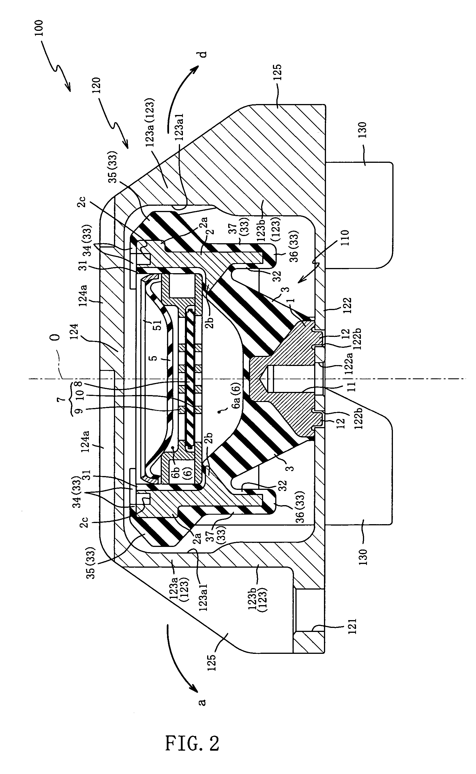
[0029]According to the hydraulic antivibration device arrangement of a first aspect of the invention because the protuberant rubber portion is provided above the vertically intermediate position of the main body member, when the protuberant rubber portion is made to abut on the sidewall parts of the car body side bracket, thereby regulating the displacement of the hydraulic antivibration device, the effect accrues that it is possible to make the input loads to the main body member and to the car body side bracket small.
[0030]More specifically, where the engine is displaced in the roll motion direction, at the hydraulic antivibration device, the upper end side of the main body member is oscillated like a pendulum relative to the boss member as a fixed point toward the sidewall parts of the car body side bracket. At that time, because of the feature that the protuberant rubber portion of the main body member is situated on the upper end side higher than the vertically intermediate position of the main body member, the distance in which the protuberant rubber portion is spaced apart from the roll center of the engine can be made longer by that amount. If so, inasmuch as a roll moment is determined by the product of a distance and a force, it is possible to make a reaction force to impingement of the protuberant rubber portion smaller and consequently, it is possible to make input loads to the main body member and the car body side bracket small by that amount.
[0031]As a result of that, it is possible not only to enhance the durability, but also to lower stiffness and strength required for respective constituent elements, and consequently, the effect accrues that it is possible to make them thin-walled by that amount, thus making the overall arrangement lightweight. Further if the reaction force to impingement upon action of the rubber stopper member can be diminished as mentioned above, it is possible to suppress the vibrations input through the car body side bracket to the body frame and hence, the effect accrues that it is possible to reduce the generation of booming noise by that amount.
[0032]Further because of such configuration of the protuberant rubber portion that assumes a transversely elongated shape extending straight in the width direction of the sidewall parts of the car body side bracket while facing the sidewall parts in a spaced relation of a definite distance, the effect accrues that it is possible to secure simultaneously its pressure-receiving area and the distance spacing apart from the roll motion center.
[0033]As a consequence, due to enlargement of the pressure-receiving area, a dispersion effect of the input load can be obtained, so that it is possible to enhance the durability. On the other hand, due to the securement of the spacing distance, it is possible to make the input loads to the main body member and to the car body side small thereby achieving a weight reduction and a reduction of booming noise simultaneously.
[0034]The car body side bracket includes the sidewall parts each of which consists of an abutment sidewall portion having an abutment face, on which the protuberant rubber portion of the rubber stopper member abuts, and a thick-walled sidewall portion formed to be more thick-walled than the abutment sidewall portion, wherein the abutment face of the abutment sidewall portion is depressed from the inner face of the thick-walled sidewall portion toward receding from the outer surface of the main body member.

Problems solved by technology

However, a problem with the hydraulic antivibration device of this type was that because of the construction that the elastic partition membrane is made to impinge (abut) on the displacement-regulating members, the displacement-regulating members oscillate upon impinging, which oscillation is transmitted to the body frame to generate a strange sound (noise).

Method used


Image

  • Hydraulic antivibration device arrangement, hydraulic antivibration device, and car body side bracket
  • Hydraulic antivibration device arrangement, hydraulic antivibration device, and car body side bracket
  • Hydraulic antivibration device arrangement, hydraulic antivibration device, and car body side bracket

Examples


first embodiment

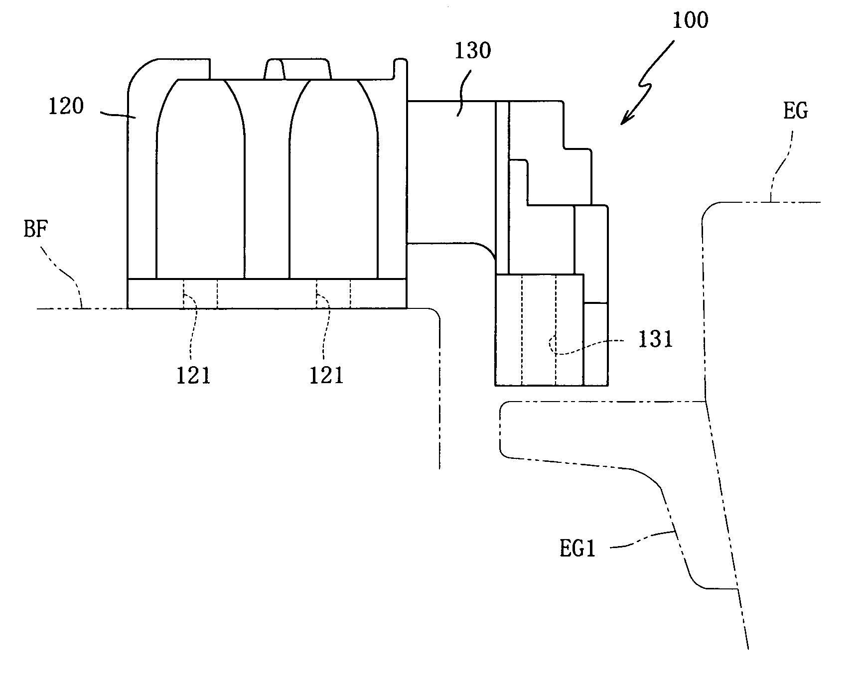
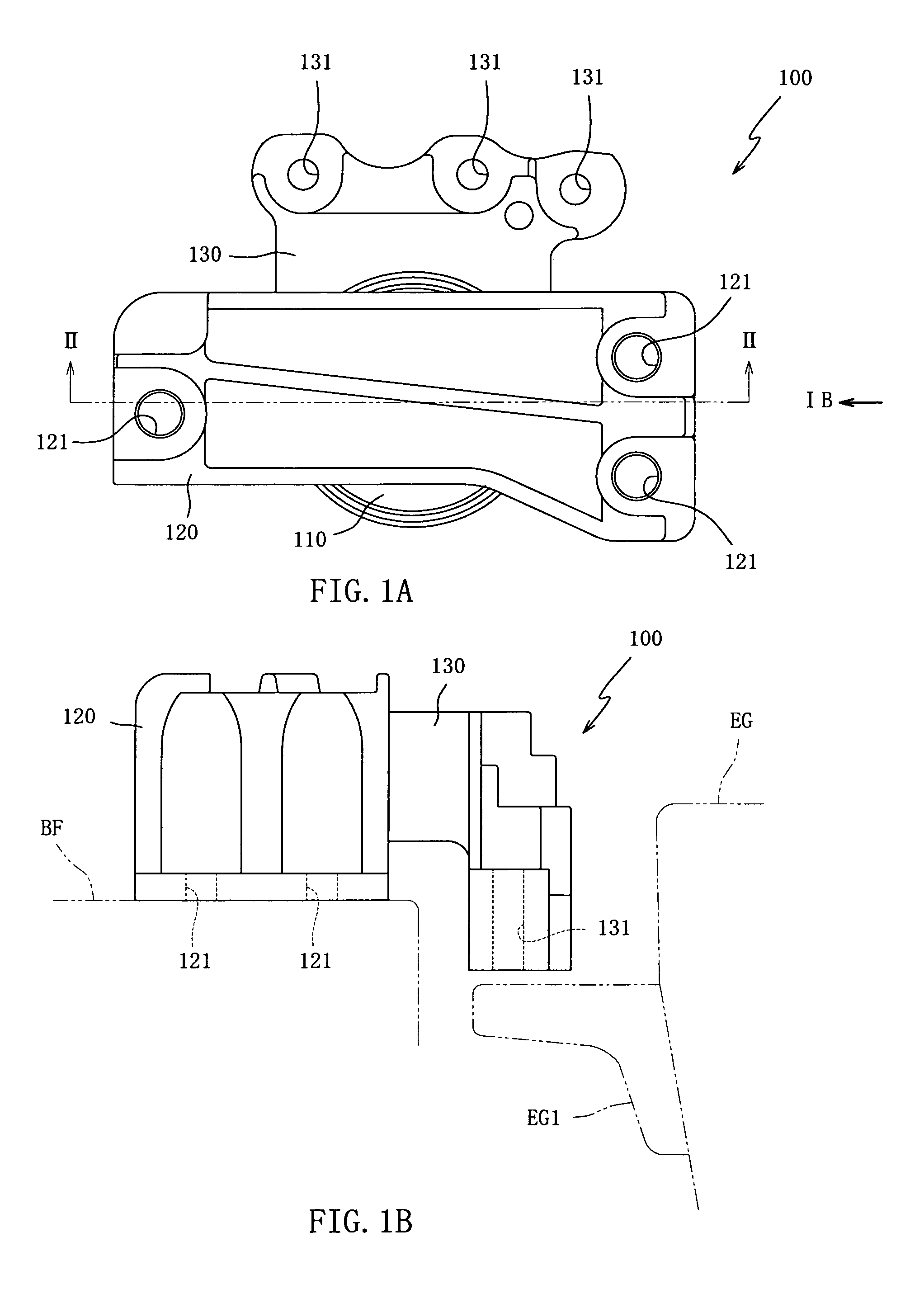
[0067]Preferred embodiments of the invention will be hereinafter described with reference to the accompanying drawings. FIG. 1(a) is a top plan view of the hydraulic antivibration device arrangement 100 in a first embodiment, and FIG. 1(b) is a side elevation of the hydraulic antivibration device arrangement 100 when viewed from the arrow mark direction Ib in FIG. 1(a).

[0068]The hydraulic antivibration device arrangement 100 is a hydraulic style vibration isolator for supporting the engine EG for automobiles in a cantilever suspended manner so as to prevent vibrations of the engine EG from being transmitted to the body frame BF. As shown in FIG. 1, it is mainly made up of the hydraulic antivibration device 110, the car body side bracket 120 connecting the hydraulic antivibration device 110 to the body frame BF side, and the engine side bracket 130 connecting the hydraulic antivibration device 110 to the engine EG side.

[0069]The car body side bracket 120 is adapted to be locked and f...

second embodiment

[0155]One piece of the protruding pin 212 in the second embodiment is provided from the boss member 1 as illustrated in FIG. 8(a), and configured in an elongated hole shape having linear lines mutually parallel with both lateral faces, as viewed in the front elevation.

[0156]On the other hand, the slit portion 222b is, as shown in FIG. 8(b), formed as a recessed groove or slot, which is extended rectilinearly from a marginal edge portion of the bottom face part 122. The width of the slit portion 222b is formed to be the same as or somewhat larger than the width dimension of the protruding pin 212. The depth of the slit portion 222b is made shallower than the height of the protruding pin 212, but the depth may be made deeper than the height.

[0157]The slit portion 222b is formed, at its terminal end in the extended direction, with the abutment portion 222b1 in a semicircular shape, as illustrated in FIG. 8(b), and constructed so that the bolt through-hole 122a of the bottom face part 1...


PUM


Abstract

A hydraulic antivibration device arrangement capable of achieving a downsizing and weight reduction, and a reduction of booming noise by suppressing a reaction force to impingement upon stopper action is provided. By disposing a protuberant rubber portion 35 at an upper end of a main body member 2, its spacing distance from a roll center can be lengthened, the reaction force to impingement can be diminished, and input load to the main body member 2 can be diminished. Consequently, reduction of rigidity and strength required for respective components as well as enhancement of durability is possible, which permits to make the components thin-walled thereby making a hydraulic antivibration device arrangement 100 lightweight as a whole. Diminishing of such reaction force upon stopper action also enables vibrations input through a car body side bracket 120 to the body frame to be suppressed, thereby reducing the generation of booming noise.

Description

TECHNICAL FIELD[0001]This invention relates to a hydraulic antivibration device arrangement, a hydraulic antivibration device and a car body side bracket, and more particularly, to such hydraulic antivibration device arrangement, hydraulic antivibration device and car body side bracket that are capable of achieving a downsizing and weight reduction and a reduction of booming noise by suppressing a reaction force to impingement upon stopper action.BACKGROUND ART[0002]As an antivibration device for supporting and fixing a vibration generator such as an automotive engine or transmission so as not to transmit vibrations thereof to a vehicle body frame, hydraulic style antivibration devices are known.[0003]Hydraulic antivibration devices each have a liquid-sealed chamber comparted by partition means into a first and a second liquid chambers, which are put in communication with each other through an orifice, and perform both a vibration attenuating function and a vibration insulating func...

Claims


Application Information

Patent Timeline
Patent Type & Authority Patents(United States)
IPC IPC(8): F16F7/00
CPCF16F13/108F16F13/101
Inventor YAMAMOTO, HIKOFUMITAKASHIMA, YUKIO
Owner TOYO TIRE & RUBBER CO LTD
Learn More