Center pillar weather strip

a weather strip and center pillar technology, applied in the field of center pillar weather strips, can solve the problems of increased closing load, low door closing load, unpreferable configuration, etc., and achieve the effect of improving sealing property between the center pillar weather strip and the center pillar, reducing the front door closing load, and easy bendability

Active Publication Date: 2015-10-01
TOYODA GOSEI CO LTD
View PDF5 Cites 6 Cited by
  • Summary
  • Abstract
  • Description
  • Claims
  • Application Information

AI Technical Summary

Benefits of technology

[0033]The front side seal lip extends from the connection portion between the front side linkage part and the hollow seal part to the extending direction of the hollow seal part. Thus, the sealing property between the center pillar weather strip and the center pillar is improved. The front side seal lip is formed in a shape curved convex to the

Problems solved by technology

Accordingly, the door closing load increases and hence such a configuration is unpreferable.
Thus, the problem is to provide a center pillar weather strip resulting in a low door-closing lo

Method used


Image

  • Center pillar weather strip
  • Center pillar weather strip
  • Center pillar weather strip

Examples


first embodiment

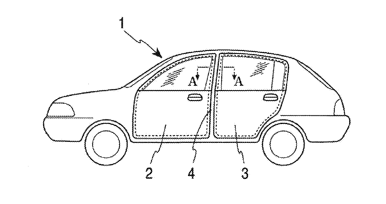
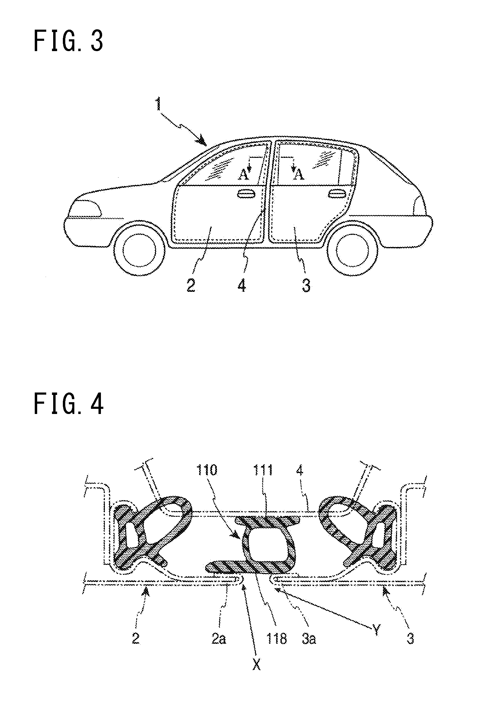
[0039]FIG. 1 shows the present invention. FIG. 3 is a side view of an automobile. As shown in FIG. 3, a center pillar 4 is provided near the center of a side surface of a car body 1 of an automobile. Then, a gap is generated between the rear end 2a of the front door 2 and the front end 3a of the rear door 3 in the portion of the center pillar 4. A center pillar weather strip 10 for sealing the gap is attached to the center pillar 4.

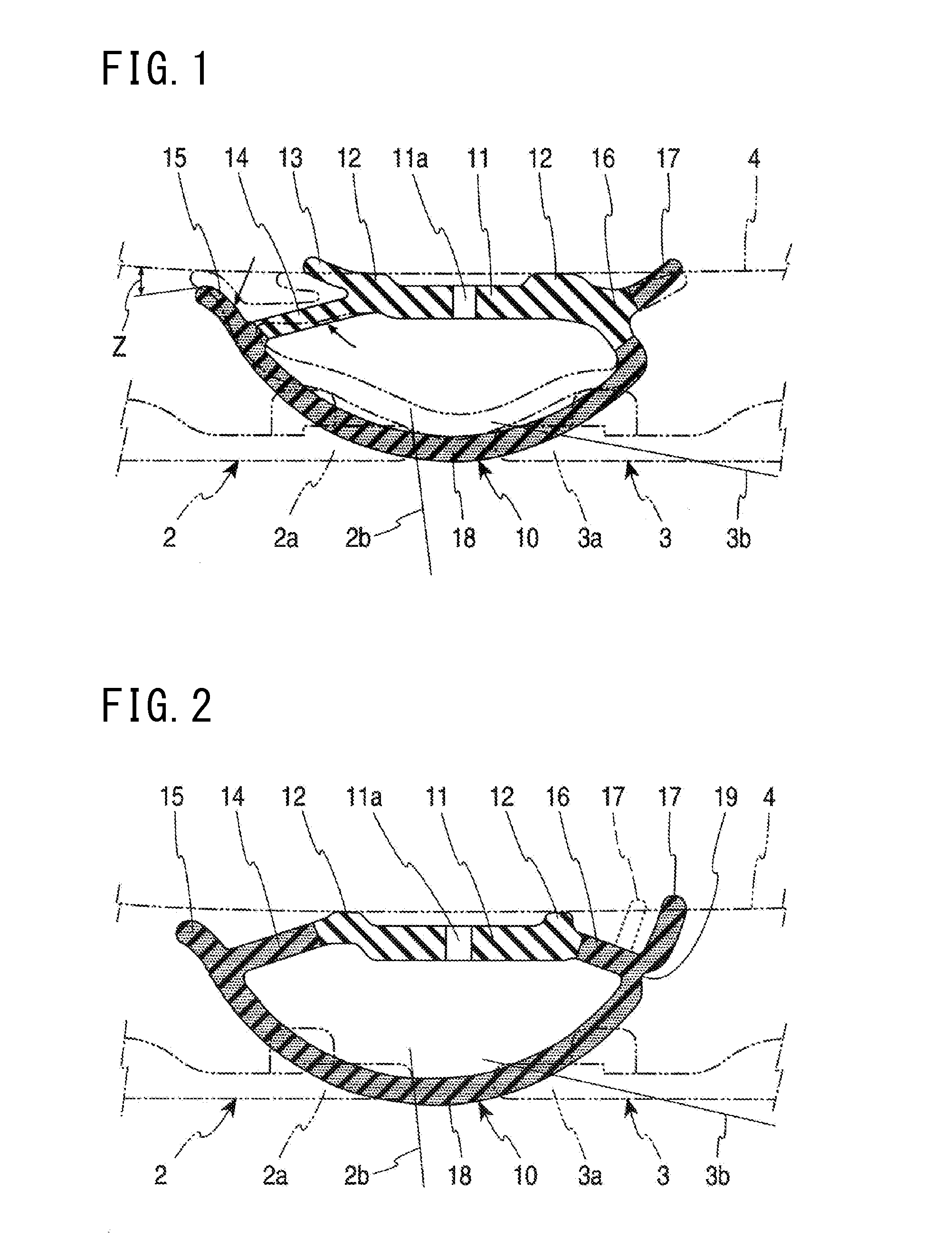
[0040]As shown in FIG. 1, the center pillar weather strip 10 according to the first embodiment of the present invention includes: an attachment base 11 attached to a center pillar 4; a front side linkage part 14 extending obliquely upward in the front direction of the car body 1 from the attachment base 11; a rear side linkage part 16 extending from the attachment base 11 to the rear direction of the car body 1; and a hollow seal part 18 linked to tips of the front side linkage part 14 and the rear side linkage part 16 and formed in a shape curved convex ...

second embodiment

[0056]The rear side linkage part 16 extends obliquely upward from the rear side tip of the attachment base 11, then the rear side linkage part 16 and the hollow seal part 18 are linked to each other, and then the rear side seal lip 17 extends from the connection portion between the rear side linkage part 16 and the hollow seal part 18 toward the extending direction of the hollow seal part 18. Thus, the tip of the rear side seal lip 17 can abut against the center pillar 4 and hence the sealing property between the center pillar weather strip 10 and the center pillar 4 is improved. In the second embodiment, the hollow seal part 18, the rear side linkage part 16, the rear side seal lip 17, and the front side linkage part 14 are formed from a sponge material. The rear side seal lip 17 and the front side linkage part 14 may be formed from a solid material.

[0057]A deformation dividing part 19 for not transmitting to the hollow seal part 18 the influence of deformation of the rear side sea...


PUM


Abstract

A center pillar weather strip attached to a center pillar includes an attachment base that attached to the center pillar, a front side linkage part that extends obliquely upward in a front direction of the car body from the attachment base, a rear side linkage part that extends from the attachment base to a rear direction of the car body, a hollow seal part that is linked to tips of the front side linkage part and the rear side linkage part and formed in a shape curved convex to a car outside, and a front side seal lip that extends from a connection portion between the front side linkage part and the hollow seal part toward an extending direction of the hollow seal part and formed in a shape curved convex to the center pillar side.

Description

CROSS-REFERENCE TO RELATED APPLICATIONS[0001]This application claims the benefit of Japanese Patent Application No. 2014-063358 (filed on Mar. 26, 2014), the entire contents of which are hereby incorporated by reference.BACKGROUND[0002]1. Technical Field[0003]The present invention relates to a center pillar weather strip attached to a center pillar of the car body of an automobile.[0004]2. Related Art[0005]As shown in FIG. 4, in the conventional art, a center pillar 4 of the car body of an automobile is provided with a center pillar weather strip 110 for sealing a gap between the rear end 2a of a front door 2 and the front end 3a of a rear door 3.[0006]The center pillar weather strip 110 includes: an attachment base 111 attached to the center pillar 4; and a hollow seal part 118 having a hollow shape and formed from the attachment base 111 to the vehicle outside direction[0007]In the locus of the rear end 2a of a case that the front door 2 is to be closed, the door is closed from th...

Claims


Application Information

Patent Timeline
IPC IPC(8): B60J10/08B60J10/00
CPCB60J10/081B60J10/0014B60J10/0062B60J10/277B60J10/7775B60J10/84
Inventor SOBUE, HIROSHINOJIRI, MASATOSHI
Owner TOYODA GOSEI CO LTD
Why Eureka
Try Eureka