
Expeditious and low cost testing of RFID ICs

a technology of integrated circuits and functional tests, applied in radiofrequency circuit testing, instruments, measurement devices, etc., can solve the problems of high testing costs, over-all cost of integrated circuits is the testing that is performed, and a complete test of an ic will cost more than a simple functional test of the same ic, so as to achieve rapid and inexpensive testing of rfid ics

Active Publication Date: 2007-10-09
TEXAS INSTR INC
View PDF7 Cites 10 Cited by
  • Summary
  • Abstract
  • Description
  • Claims
  • Application Information

AI Technical Summary

Benefits of technology

[0010]An advantage of a preferred embodiment of the present invention is that in a single test, the RF circuitry and non-RF circuitry of a RFID IC can be tested. Therefore, the cost of testing can be minimized.
[0011]A further advantage of a preferred embodiment of the present invention is that the single test can be implemented with a minor change to the layout of the ICs to enable the testing without increasing the cost of manufacture for the ICs. Therefore, the implementation of the present invention can be made with minimal investment in money and equipment.

Problems solved by technology

A factor in the overall cost of an integrated circuit (IC) is the testing that is performed on the IC.
In general, a complete test of an IC will cost more than a simple functional test of the same IC.
Furthermore, a test that takes an extended amount of time will result in a higher testing cost since additional testing facilities may be needed to meet production requirements.
A disadvantage of the prior art is that the use of probes to test the ICs has limited capability in testing the RF performance of the ICs.
The need for additional testing will increase the overall testing time, complexity, and cost and therefore increase the overall cost of the ICs.
Furthermore, probes are mechanical devices that are expensive and wear out with use.

Method used


Image

  • Expeditious and low cost testing of RFID ICs
  • Expeditious and low cost testing of RFID ICs
  • Expeditious and low cost testing of RFID ICs

Examples


Embodiment Construction

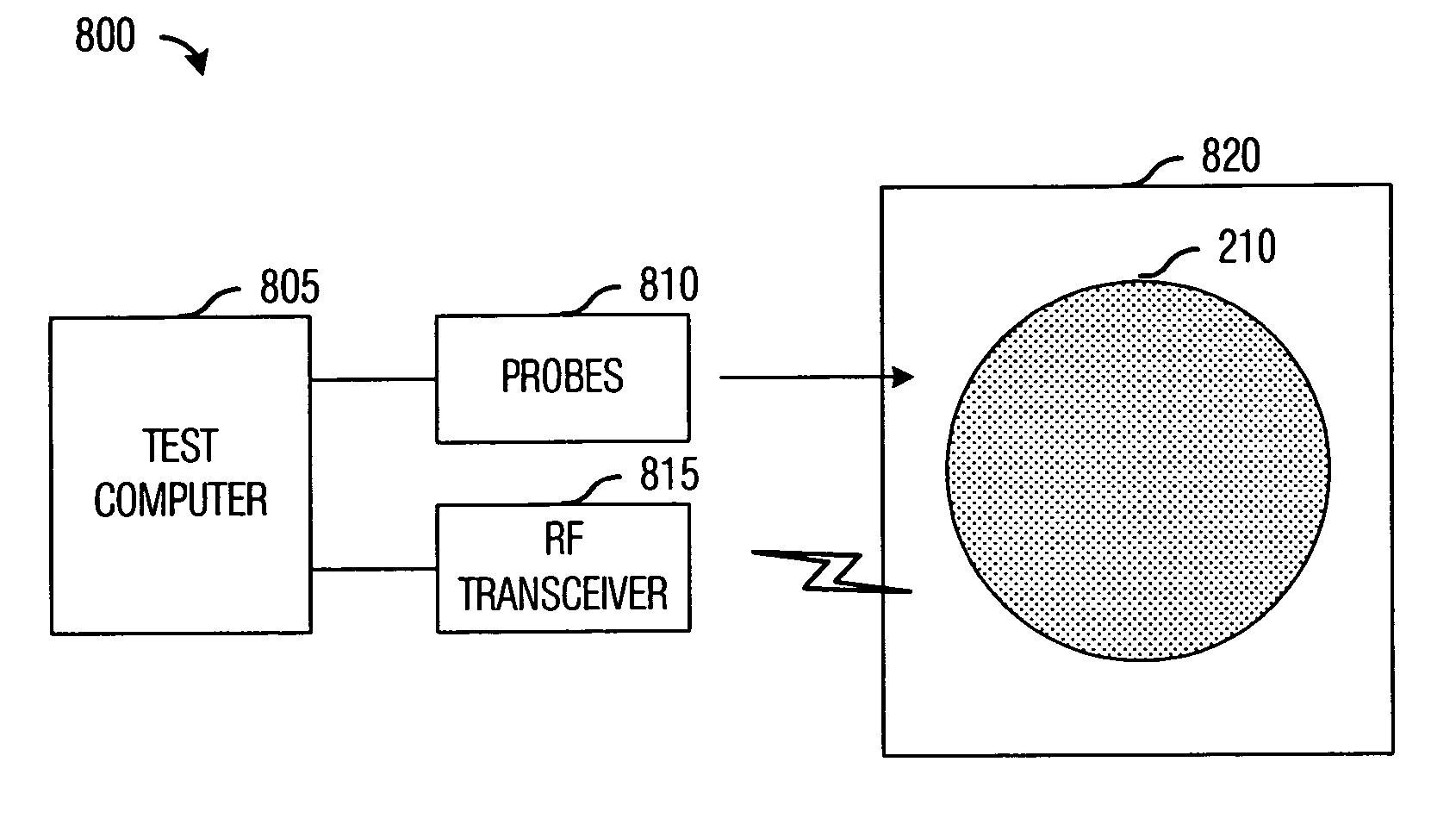
[0022]The making and using of the presently preferred embodiments are discussed in detail below. It should be appreciated, however, that the present invention provides many applicable inventive concepts that can be embodied in a wide variety of specific contexts. The specific embodiments discussed are merely illustrative of specific ways to make and use the invention, and do not limit the scope of the invention.

[0023]The present invention will be described with respect to preferred embodiments in a specific context, namely the production testing of RF and non-RF circuits in RFID tags. The invention may also be applied, however, to the testing of integrated circuits that feature RF circuitry in addition to non-RF circuitry without requiring the separate testing of the RF circuitry and the non-RF circuitry.

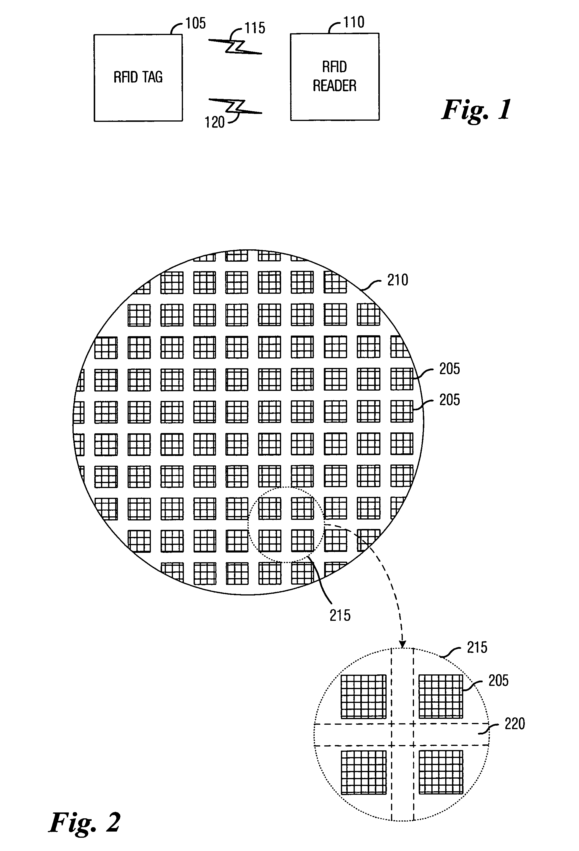
[0024]With reference now to FIG. 1, there is shown a diagram illustrating the operation of an RFID tag and reader combination. The diagram shown in FIG. 1 illustrates an RFID tag 10...


PUM


Abstract

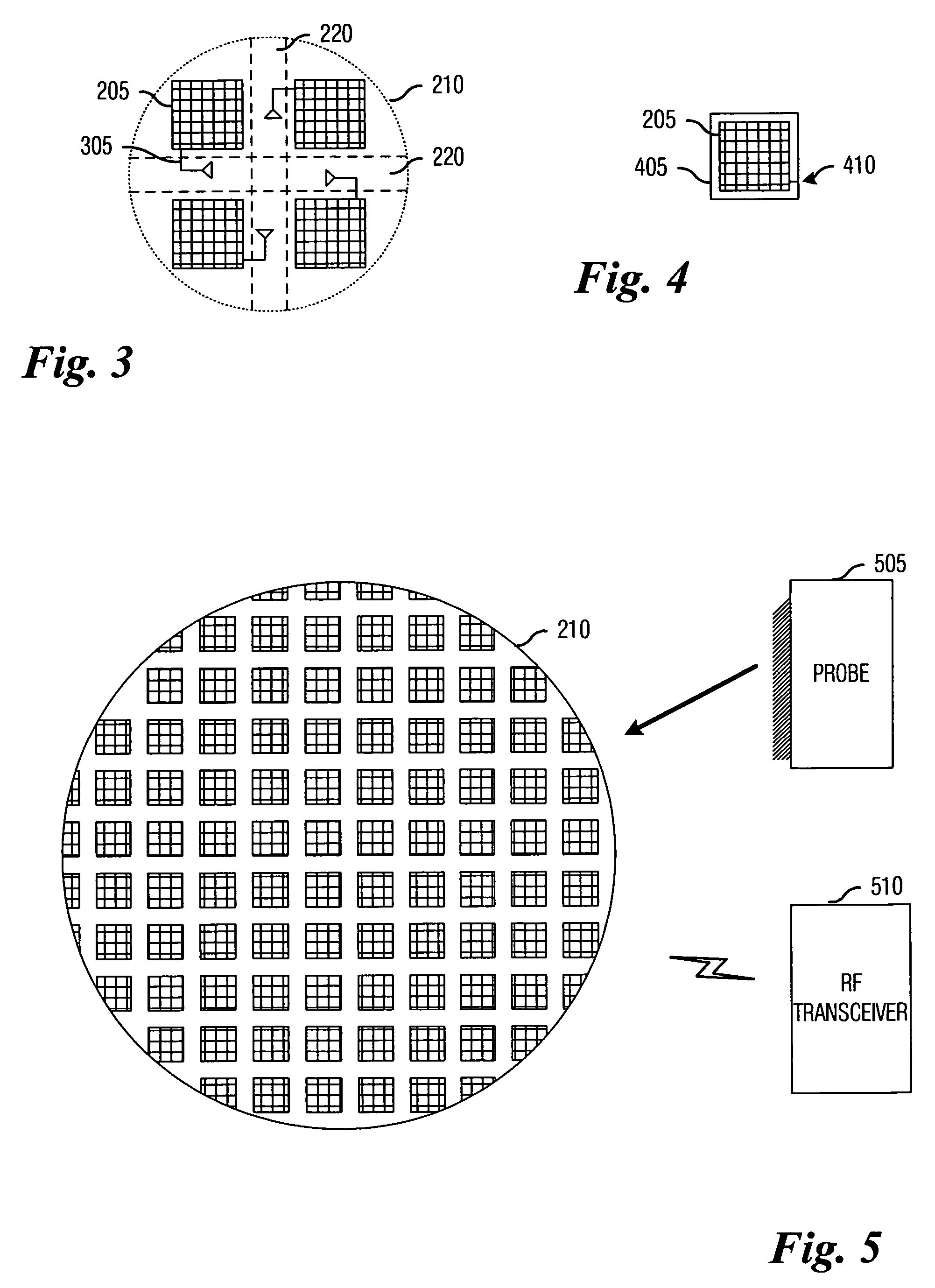
System and method for integrated circuit manufacturing. A preferred embodiment comprises transmitting a first set of data to integrated circuits (ICs) while they are in an on-wafer state and having each IC store the first set of data into memory, transmitting a second set of data to the ICs and having the ICs compare the second set of data with the first set of data stored in the memory, reading out the results of the comparisons, and marking an IC as being defective if the comparison indicates that that the first set of data did not match the second set of data. Each IC features an antenna formed in the scribe line region adjacent to the IC so that communications can take place while the IC remains on the wafer without the need to use electrical probes.

Description

TECHNICAL FIELD[0001]The present invention relates generally to a system and method for integrated circuit manufacturing, and more particularly to a system and method for rapidly and inexpensively testing radio-frequency identification (RFID) integrated circuits.BACKGROUND[0002]The use of radio-frequency identification (RFID) devices has started to become more widespread since applications in retail sales, product manufacturing, shipping, traffic management, and so forth, have started to materialize. In many of these applications, large numbers of RFID tags, individual integrated circuits with antenna, are embedded into products to enable the tracking of the products. With the possible exception of traffic management, the RFID tags have an inherent requirement to be inexpensive, so as to not negatively affect the cost of the products in which they are embedded.[0003]A factor in the overall cost of an integrated circuit (IC) is the testing that is performed on the IC. In general, a c...

Claims


Application Information

Patent Timeline
Patent Type & Authority Patents(United States)
IPC IPC(8): G01R31/26
CPCG01R31/2822G01R31/3025G01R31/311
Inventor KRAMER, BRADLEY ALLEN
Owner TEXAS INSTR INC
Learn More