Multi-spectral detector and analysis system

a detector and multi-spectral technology, applied in the direction of optical radiation measurement, fluorescence/phosphorescence, instruments, etc., can solve the problems of limiting the application of current systems, difficult to identify the nature of components, and difficult to measure the emission intensity of individual fluorescence labels to the exclusion of others

Active Publication Date: 2007-10-09
MIFTEK CORP
View PDF17 Cites 49 Cited by
  • Summary
  • Abstract
  • Description
  • Claims
  • Application Information

AI Technical Summary

Problems solved by technology

This detection process is based on the evaluation of signal intensity in a single optical band; therefore, without signal separation, it is difficult to identify the nature of the component.
The fluorescence emission of almost all organic fluorochromes is broad, making it difficult to measure the emission intensity of an individual fluorescence label to the exclusion of another.
This is the ultimate limitation of current systems.

Method used


Image

  • Multi-spectral detector and analysis system
  • Multi-spectral detector and analysis system
  • Multi-spectral detector and analysis system

Examples


Embodiment Construction

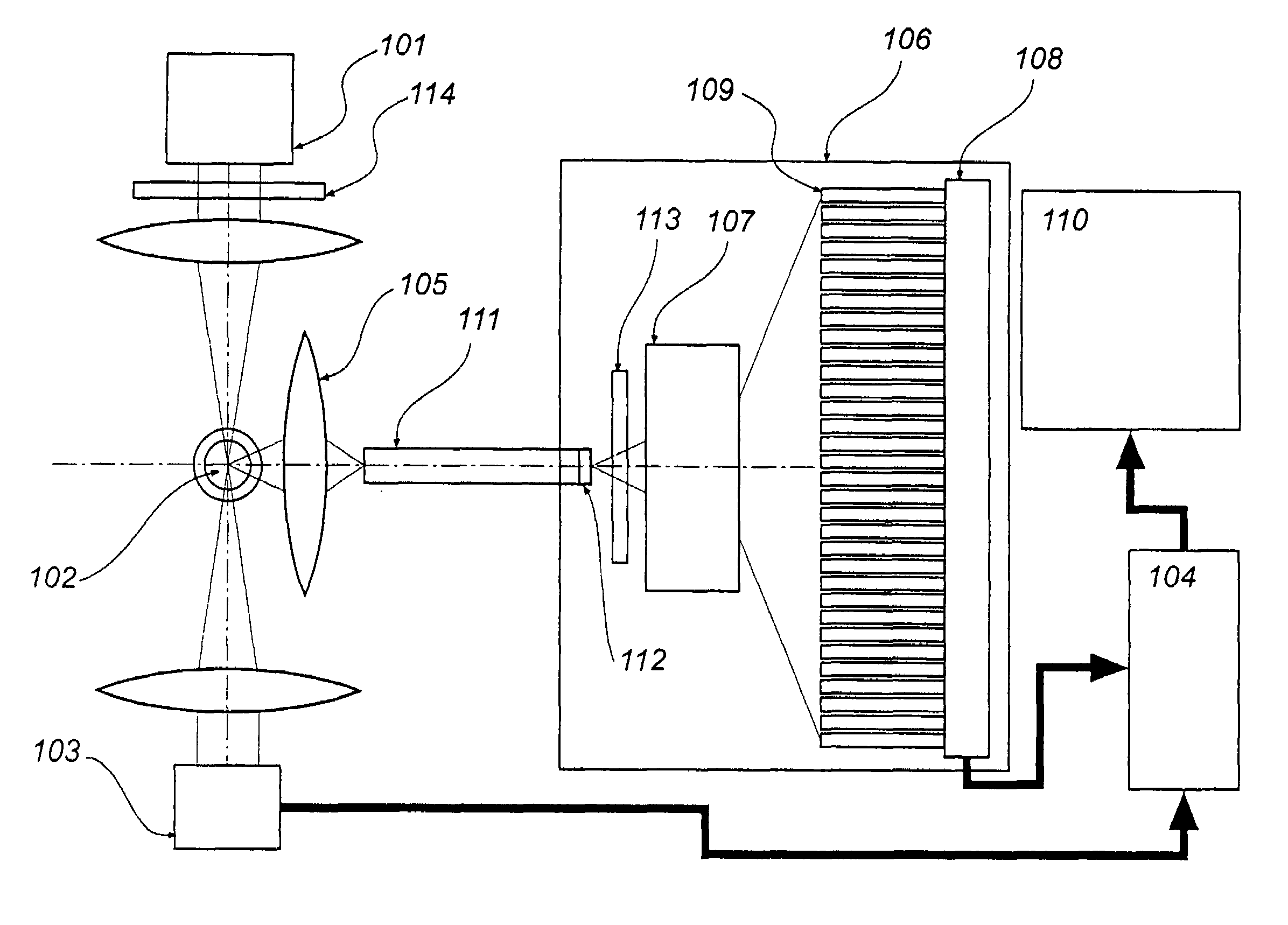
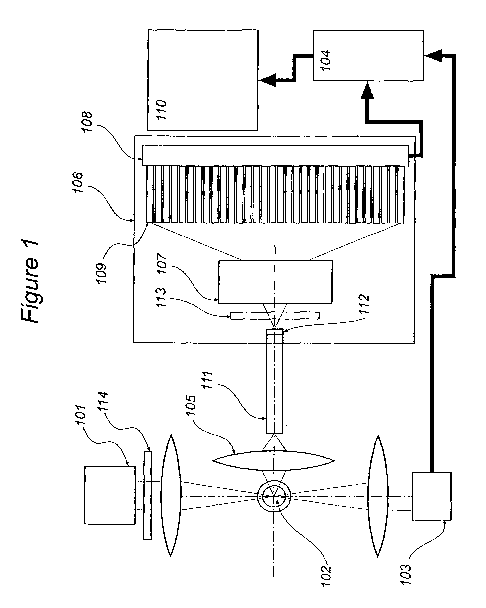
[0019]A spectral detection system may include a light source for exciting a targeted sample. The targeted sample may be a crystalline structure or a micro-particle that will luminesce. The micro-particle may be a small biological particle that is about 60 μm or less. A micro-particle may include a biological particle either alone or in combination with a marker, a tag or a stain. The biological particle may be a human, animal, or plant cell, a bacterium, a virus, etc. Luminescence may include any means that is known or becomes known suitable for exciting the targeted sample. For example, luminescence may include fluorescence, phosphorescence, or chemiluminescence. The micro-particle may be sampled in an observation region of a flow cytometer where the particle is detected. The stain, either organic or inorganic, or a luminescent protein may, be used to tag or mark the micro-particle. The marker or tag may luminesce when irradiated. The marker or tag may exhibit a characteristic spec...


PUM

PropertyMeasurementUnit
wavelengthsaaaaaaaaaa
wavelength regionaaaaaaaaaa

Abstract

A multi-spectral detection and analysis system detects and classifies a targeted sample. The system may include a light source that causes the targeted sample to luminesce. A light dispersion element disperses the luminescence to a photodetector in a photodetector array. Each photodetector in the array transmits a signal indicating a portion of the spectrum to a multi-channel collection system. The multi-channel collection system processes the signal into a digital signal and forms the digital signal into a spectral signature. A processor analyzes the spectral signature and compares the spectral signature to known spectral signatures to identify the targeted sample.

Description

PRIORITY CLAIM[0001]This application claims the benefit of U.S. Provisional Application Nos. 60 / 560,828 filed on Apr. 8, 2004, 60 / 612,382 filed on Sep. 22, 2004, and 60 / 613,175 filed on Sep. 23, 2004. The above provisional applications are incorporated herein by reference.BACKGROUND OF THE INVENTION[0002]1. Field of the Invention[0003]This invention relates to multi-spectral detectors of luminescence, and in particular to the detection of luminescence from materials that are stimulated with light sources.[0004]2. Background of the Invention[0005]Multi-spectral detector systems may detect luminescence from particles and materials that are stimulated with a light source. Such systems may further analyze the luminescence. Multi-spectral systems may include a flow cytometry system that characterizes and classifies particles of interest from heterogeneous populations. Flow cytometry interrogates a particle suspended within a stream of liquid as the particle passes through a light focusin...

Claims


Application Information

Patent Timeline
Patent Type & Authority Patents(United States)
IPC IPC(8): G01J3/30G01J3/28G01J3/36G01N15/14G01N21/05G01N21/64
CPCG01J3/2803G01J3/36G01N15/1459G01N21/645G01N2021/6482G01N2021/6439G01N21/05
Inventor ROBINSON, JOSEPH PAULRAJWA, BARTLOMIEJGREGORI, GERALDPATSEKIN, VALERY
Owner MIFTEK CORP
Why Eureka
Try Eureka