Dust tolerant windowless scanner

Inactive Publication Date: 2007-10-09
HEWLETT PACKARD DEV CO LP
View PDF12 Cites 4 Cited by
  • Summary
  • Abstract
  • Description
  • Claims
  • Application Information

AI Technical Summary

Benefits of technology

[0010]The principles of the present invention are applicable, generally, to a dust tolerant windowless scanner and its media scan assembly. According to the present invention, the scanner is windowless (or “open”), thus preventing du

Problems solved by technology

Although dust or debris on the top surface of the glass plate 304 can be easily removed, it is difficult to clean dust or debris from the inside of th

Method used


Image

  • Dust tolerant windowless scanner
  • Dust tolerant windowless scanner
  • Dust tolerant windowless scanner

Examples


Embodiment Construction

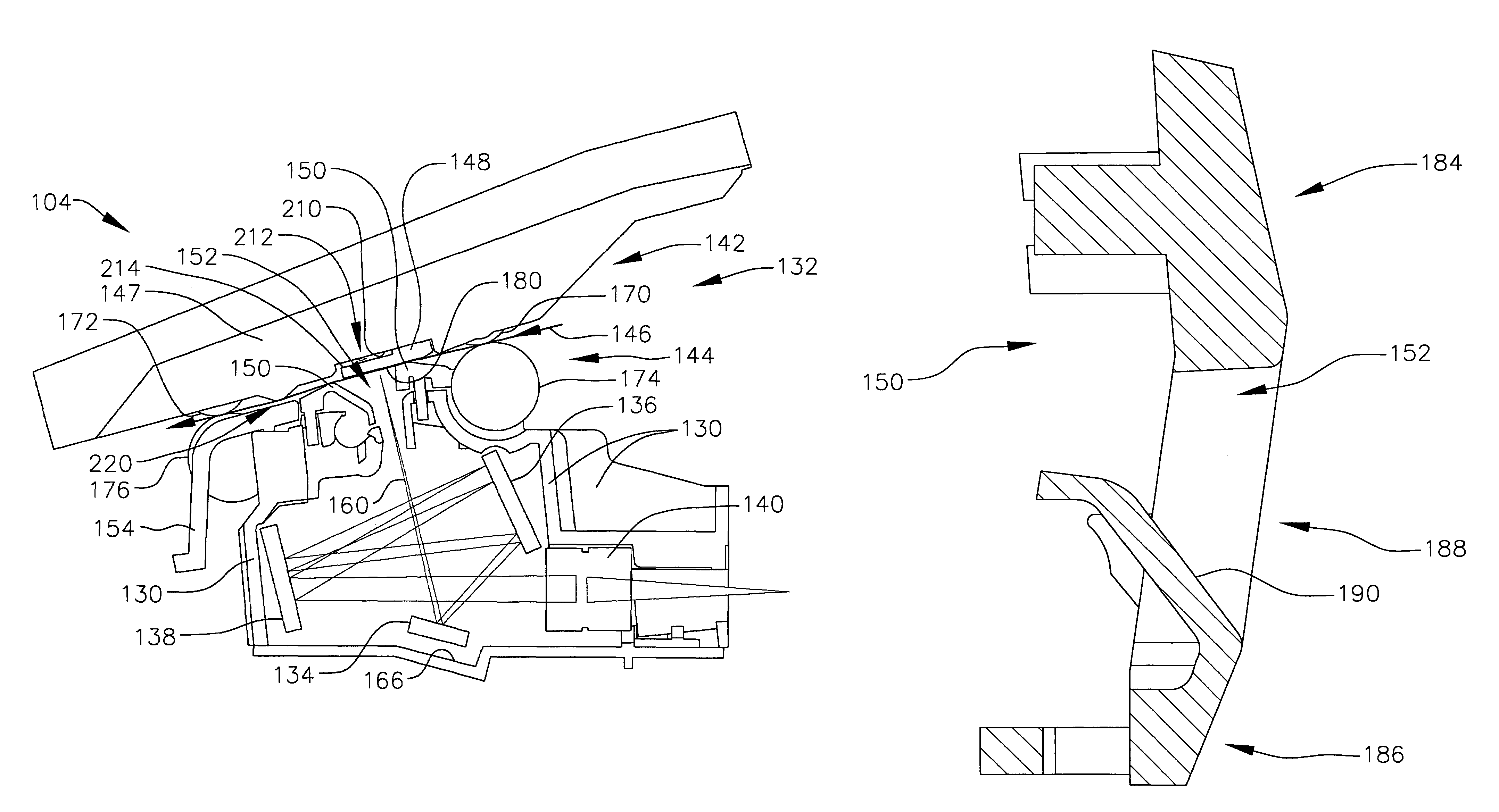
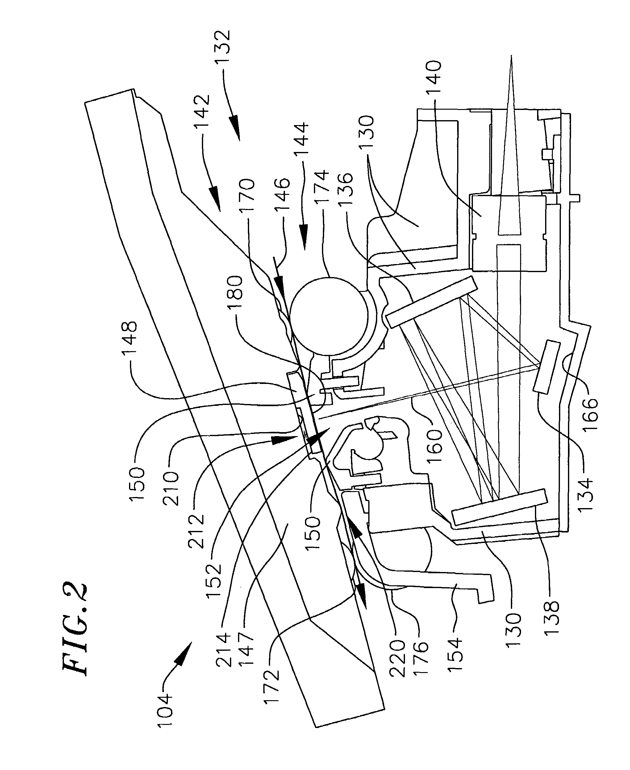
[0027]The following is a detailed description of the best presently known mode of carrying out the invention. This description is not to be taken in a limiting sense, but is made merely for the purpose of illustrating the general principles of the invention.

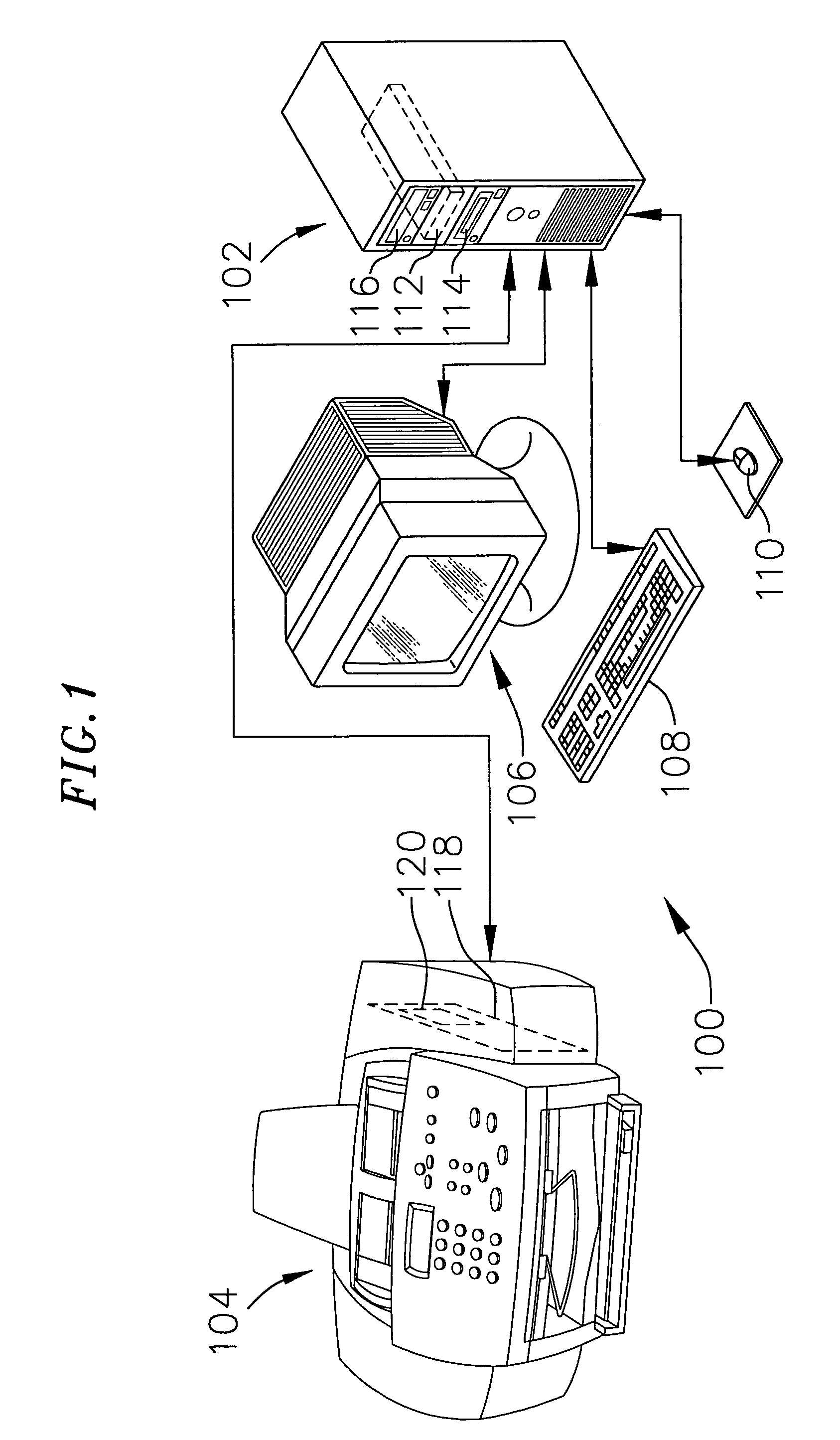
[0028]FIG. 1 shows a system 100 configured to employ the principles of the present invention. The system 100 includes a computer 102, scanner 104, monitor 106 and various user-input devices such as a keyboard 108 and a mouse 110 functionally interconnected as shown. The computer 102 comprises, for example, a personal computer (“PC”) with a hard drive 112 (shown with dashed lines), a disk drive 114 and a CD-ROM drive 116. An exemplary preferred scanner 104 comprises an “All-In-One” product such as the HP OfficeJet T Series (T45 / 65) which provides integrated printing, faxing, scanning and copying functions, all in color. The scanner 104 includes a circuit card 118 with firmware 120 (both shown with dashed lines). Algorithms utilize...


PUM


Abstract

A dust tolerant scanner without a transparent plate to support objects scanned by its media scan assembly. Other dust or debris collecting surfaces in the optical path of the scanner are positioned as far away as possible from an object focal plane of the media scan assembly. The media scan assembly includes upper and lower document feeder portions which define a media path adjacent to a reference surface of the upper portion. The lower document feeder portion includes a media conformance member which positions pieces of media against the reference surface as the pieces of media are advanced along the media path. The media conformance member includes ramp portions and an aperture which provides an optical path between the object focal plane and a sensor focal plane within the scanner.

Description

CROSS-REFERENCE TO RELATED APPLICATIONS[0001]This application is a continuation of U.S. patent application Ser. No. 09 / 521,192 filed on Mar. 7, 2000 now U.S. Pat. No. 6,657,751.BACKGROUND OF THE INVENTION[0002]1. Field of Invention[0003]The present invention relates generally to a dust tolerant windowless scanner and, more specifically, to a dust tolerant windowless scanner and its media scan assembly.[0004]2. Description of the Related Art[0005]Scanners typically include an array of optical sensor elements and a scan area (e.g., plate of glass) where an object to be imaged by the sensor elements is positioned. An optical path including, for example, lenses and mirrors, spans between the sensor elements and the scan area.[0006]Referring to FIG. 3, a conventional scanner 300 includes a main housing 302, a glass plate 304, mirrors 306, 308, 310 and a lens 312 configured as shown. An optical path 314 of the scanner 300 begins at an object focal plane 316 at the top surface of the glass...

Claims


Application Information

Patent Timeline
IPC IPC(8): H04N1/04H04N1/40H04N1/00
CPCH04N1/04H04N1/0057
Inventor MAURER, CRAIG A.WILLIAMS, SCOTT F.ZIMMERMAN, JON LEESCHMIDT, JACKDOAN, ALPHA
Owner HEWLETT PACKARD DEV CO LP
Why Eureka
Try Eureka