

Endoscopic objective optical system, and imaging system using the same
- Summary
- Abstract
- Description
- Claims
- Application Information
AI Technical Summary
Benefits of technology
Problems solved by technology
Method used
Image

Examples
examples 7-15
[0120]FIGS. 13-21 are optical path representations for the endoscopic objective optical systems according to Examples 7-15, respectively, and FIGS. 28-36 are aberration diagrams, as in FIG. 22, for the endoscopic objective optical systems according to Examples 7-15.
[0121]Details of these examples are not explained, because Examples 7, 8 and 9 (FIGS. 13, 14 and 15) are much the same as in Example 2 (FIG. 5); Examples 10-13 (FIGS. 16-19) are much the same as in Example 1 (FIG. 4); and Examples 14 and 15 (FIGS. 20 and 21) are much the same as in Example 3 (FIG. 6).
[0122]While the endoscopic objective optical systems of Examples 1-15 are all standardized at a focal length of 1 mm for the purpose of brevity, it is understood that they should preferably have a focal length of about 1 to 3 mm and an image height of about 0.5 to 2 mm d in actual applications.
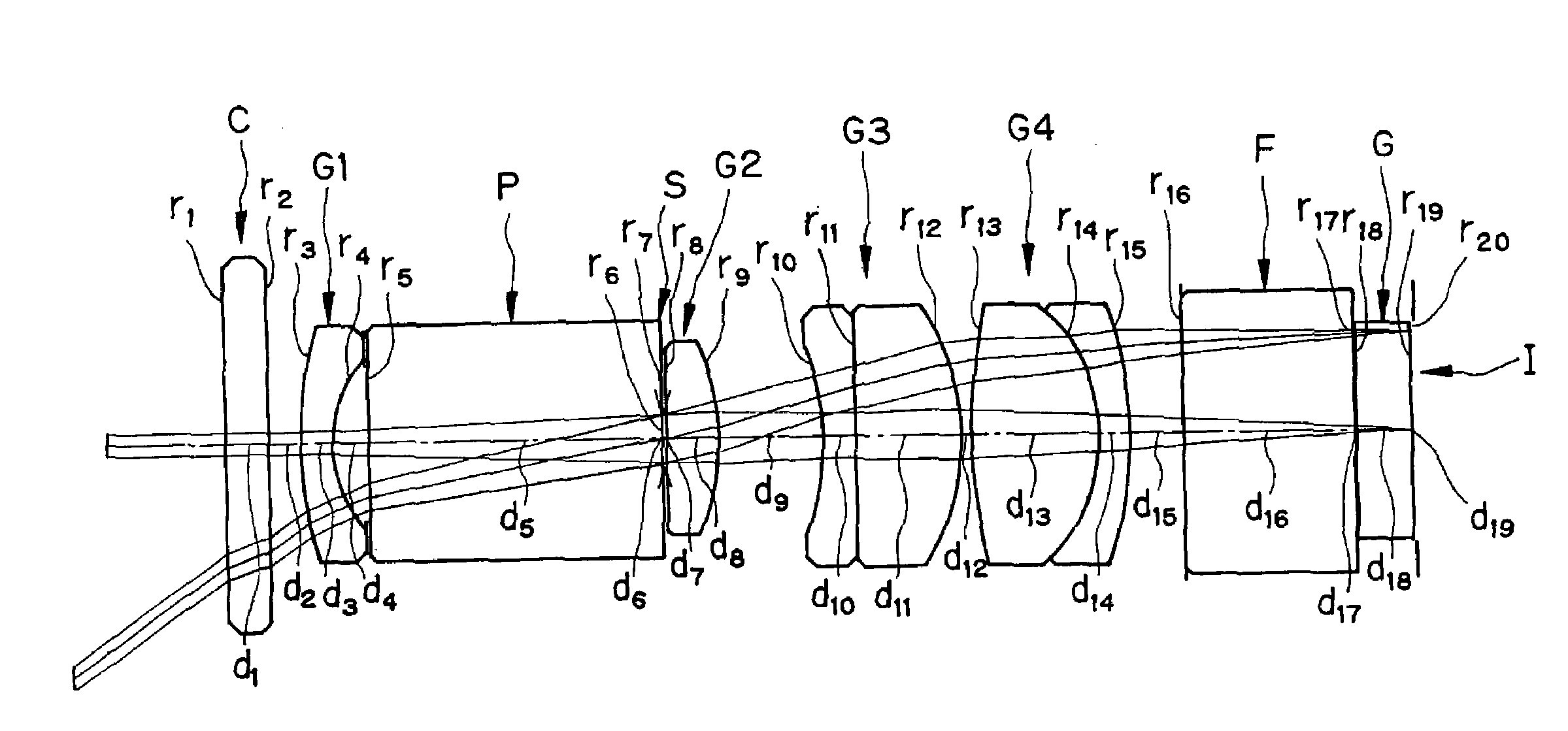
[0123]Regarding Examples 1 to 15 of the invention, lens data are now given below. Here, the symbols used with the lens data but not he...
example 1
[0124]
r0 = ∞ (Object Plane)d0 = 14.4568r1 = ∞d1 = 0.2754nd1 = 1.76820νd1 = 71.79r2 = ∞d2 = 0.2065r3 = 2.5155d3 = 0.2065nd2 = 1.88300νd2 = 40.76r4 = 0.7993d4 = 0.2341r5 = ∞d5 = 1.9276nd3 = 1.80610νd3 = 40.95r6 = ∞d6 = 0.0000r7 = ∞ (Stop)d7 = 0.0207r8 = ∞d8 = 0.3442nd4 = 1.88300νd4 = 40.76r9 = −1.4918d9 = 0.6884r10 = −1.5696d10 = 0.2134nd5 = 1.84666νd5 = 23.78r11 = ∞d11 = 0.6884nd6 = 1.88300νd6 = 40.76r12 = −1.4918d12 = 0.0688r13 = 3.6989d13 = 0.8261nd7 = 1.51633νd7 = 64.14r14 = −1.0884d14 = 0.2065nd8 = 1.84666νd8 = 23.78r15 = −2.4102d15 = 0.3373r16 = ∞d16 = 1.1015nd9 = 1.51399νd9 = 75.00r17 = ∞d17 = 0.0138nd10 = 1.51000νd10 = 63.00r18 = ∞d18 = 0.3442nd11 = 1.51633νd11 = 64.14r19 = ∞d19 = 0.0207r20 = ∞ (Image plane)F = 1.00FNO = 6.058Ih = 0.6272ω (°) = 69.425D (%) = −9.475α (°) = 3.038
example 2
[0125]
r0 = ∞ (Object Plane)d0 = 14.9395r1 = ∞d1 = 0.2988nd1 = 1.76820νd1 = 71.79r2 = ∞d2 = 0.2134r3 = 4.5420d3 = 0.1921nd2 = 1.88300νd2 = 40.76r4 = 0.8204d4 = 0.1921r5 = ∞d5 = 2.5610nd3 = 1.88300νd3 = 40.76r6 = ∞ (Stop)d6 = 0.0128r7 = ∞d7 = 0.4695nd4 = 1.72916νd4 = 54.68r8 = −1.7253d8 = 0.2988r9 = 1.6404d9 = 0.5976nd5 = 1.88300νd5 = 40.76r10 = ∞d10 = 0.2134r11 = −1.5832d11 = 0.6701nd6 = 1.75520νd6 = 27.51r12 = 1.5832d12 = 0.1067r13 = ∞d13 = 0.5976nd7 = 1.88300νd7 = 40.76r14 = −1.6404d14 = 0.0427r15 = 2.4889d15 = 0.2134nd8 = 1.84666νd8 = 23.78r16 = 1.0321d16 = 0.6360nd9 = 1.48749νd9 = 70.23r17 = −2.8462d17 = 0.2220r18 = ∞d18 = 0.6829nd10 = 1.51400νd10 = 75.00r19 = ∞d19 = 0.0085nd11 = 1.51000νd11 = 63.00r20 = ∞d20 = 0.2134nd12 = 1.51633νd12 = 64.14r21 = ∞d21 = 0.0128r22 = ∞ (Image plane)F = 1.00FNO = 7.925Ih = 0.6432ω (°) = 69.016D (%) = −6.353α (°) = 5.468
PUM
 Abstract
Description
Claims
Application Information