
Image display device with built-in loudspeakers

a display device and loudspeaker technology, applied in the direction of electrical transducers, stereophonic arrangments, television systems, etc., can solve the problem of not being able to deliver high-quality sound reproduction, and achieve the effect of improving the low-frequency sound quality, stable reproduction sound quality, and reducing sound quality

Inactive Publication Date: 2007-10-09
SHARP KK
View PDF24 Cites 40 Cited by
  • Summary
  • Abstract
  • Description
  • Claims
  • Application Information

AI Technical Summary

Benefits of technology

The present invention provides an image display device with a loudspeaker system that can produce stable and high-quality sounds. The device includes a main body for displaying video, a first loudspeaker for low-frequency sounds, and a second pair of loudspeakers for middle and high-frequency sounds. The loudspeakers are arranged in a way that the first loudspeaker is absorbed by the stand and reflected from it, eliminating the possibility of decreased sound quality due to the floor. The loudspeakers have a unique design that creates a visually symmetrical and fine external appearance while maintaining mechanical strength. The device can also have a thinner design by separating the loudspeakers from the stand. The first loudspeaker has a larger aperture than the second loudspeakers. The ratio of the whole area of through-holes relative to the first loudspeaker is greater than the ratio of the whole area of through-holes relative to the second loudspeakers.

Problems solved by technology

Because of the absence of a loudspeaker box, the television receiver has a small dynamic range of its sound system and therefore cannot deliver high quality sound reproduction.

Method used


Image

  • Image display device with built-in loudspeakers
  • Image display device with built-in loudspeakers
  • Image display device with built-in loudspeakers

Examples


Embodiment Construction

[0036]Preferred embodiments of the present invention will be described below with reference to accompanying drawings.

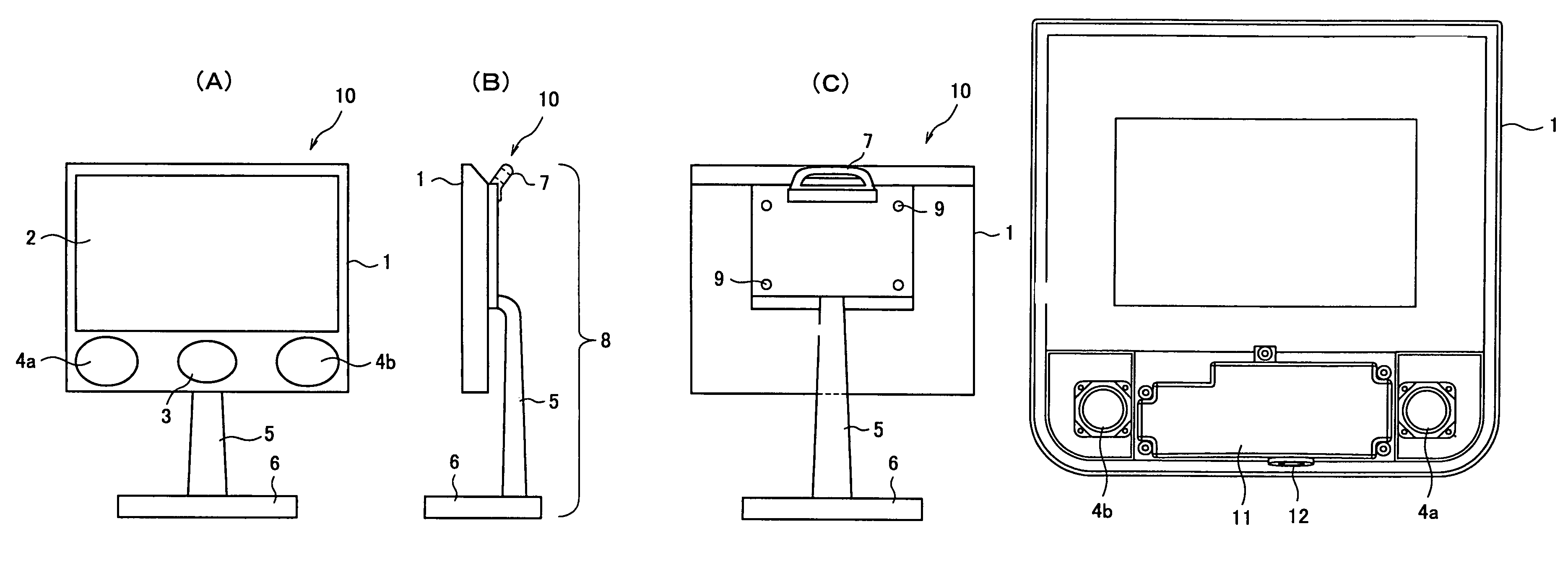
[0037]FIG. 5 shows a television receiver according to an embodiment of the present invention. FIG. 5(A) is a front view, FIG. 5(B) is a right-side view and FIG. 5(C) is a rear view of the television receiver. The television receiver 10 has a main display body 1 using a liquid crystal display (LCD) or a plasma display panel (PDP) and the like as a thin display unit 2, wherein the main body 1 is further provided at its front lower portion with a pair of left and right loudspeakers 4a, 4b for reproducing sounds of middle and high frequencies and a loudspeaker (woofer) 3 for reproducing sounds of low frequency placed between the pair of loudspeakers 4a and 4b.

[0038]A stand 8 is composed of a support 5, a base 6 and a handle unit 7. The stand 8 can be removably secured at its upper portion with machine screws 9 to the rear surface of the main display body 1. Thus, the mai...


PUM


Abstract

An image display device has a main display body provided with a thin display unit, a low-frequency loudspeaker (woofer) and two middle and high frequency loudspeakers (tweeters) and a stand supporting the main display body. The stand has a base being just opposite at its top surface to a duct outlet of the woofer, thereby sound emitted from the duct can be constantly absorbed by and reflected from the base. A housing containing the first loudspeaker and a pair of the second loudspeakers has a plurality of through holes formed in a first area corresponding to an aperture of each loudspeaker and a plurality of blind holes formed in a second area surrounding the first area, wherein the second area for the first loudspeaker is different in peripheral shape and / or size from the second area for each of the second pair of loudspeakers.

Description

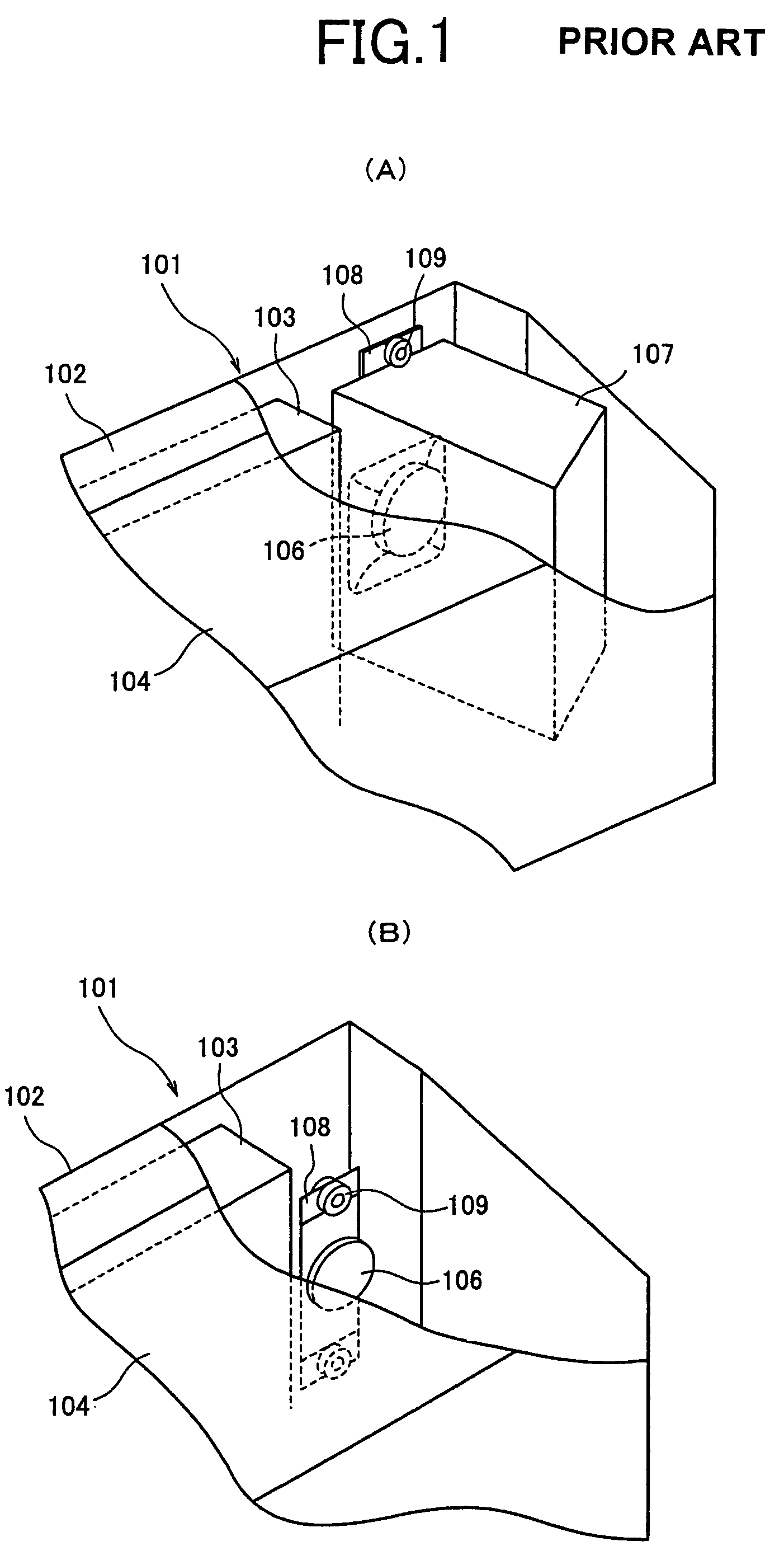
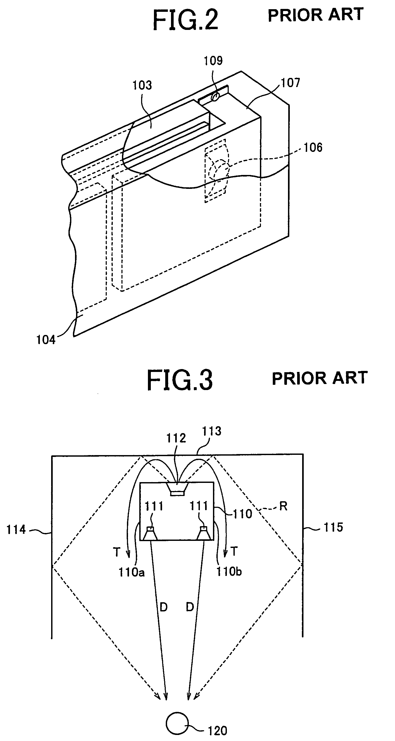
FIELD OF THE INVENTION[0001]The present invention relates generally to an image display device and, more specifically, to a personal computer equipped with a thin display such as a liquid crystal display (LCD) device and a plasma display panel (PDP) device or an image display device applicable to a display portion of a television receiver.BACKGROUND OF THE INVENTION[0002]In recent years, the production of small and thin electronic devices has been advanced with development of electronic technology and a growing consumers' demand for thinner and smaller home electronic apparatuses. Indeed, various kinds of television receivers are now available, which are constituted by using thin CRTs, LCD panels and plasma-display panels. The television receivers have video reproducing function and sound reproducing function. The latter function is realized generally by means of loudspeakers.[0003]FIGS. 1 and 2 illustrate a typical exemplary structure of a loudspeaker portion of a conventional tele...

Claims


Application Information

Patent Timeline
Patent Type & Authority Patents(United States)
IPC IPC(8): H04R25/00H04N5/64H04N5/66H04R1/26H04R1/28H04R5/02
CPCH04N5/642H04R1/2857H04R5/02H04R1/26H04N5/66H04R2499/15H04N5/64H04R1/00H04R1/02
Inventor TAMURA, ICHIROOHTSUKA, KOHJI
Owner SHARP KK
Learn More