Hydraulic controller and hydraulic drive unit provided with said hydraulic controller

a technology of hydraulic controller and hydraulic drive unit, which is applied in the direction of fluid coupling, servomotor, water cleaning, etc., can solve the problems of difficult to reduce the number of parts of the hydraulic drive unit, reduce assembly service life, and generate noise, so as to reduce the number of parts required, reduce the effect of noise generated by the operation of the device and long service li

Active Publication Date: 2007-10-16
KYB CORP
View PDF14 Cites 39 Cited by
  • Summary
  • Abstract
  • Description
  • Claims
  • Application Information

AI Technical Summary

Benefits of technology

[0007]The present invention has been made in view of the above situation, and accordingly, preferred embodiments of the invention provide a hydraulic controller capable of reducing noise and the number of parts and realizing a long service life, and a hydraulic drive unit provided with the hydraulic controller.
[0010]Preferred embodiments of hydraulic controllers and hydraulic drive units of the type described herein can reduce noise generated by the devices' operations, reduce the number of parts required for such assemblies, and achieve long operational service lives.

Problems solved by technology

Otherwise, because the output shaft of the electric motor is connected to the driving shaft of hydraulic pump later, the rotation center cannot be aligned, which poses a problem in that noise is generated when the motor and pump are driven, and an improper force acts in the interior and hence the assembly's service life is reduced.
Also, a problem is present in that it is difficult to reduce the number of parts of the hydraulic drive unit and thereby to reduce its cost.
Also, in the case where an electric motor housing for disposing the electric motor, a hydraulic pump housing for installing the hydraulic pump, and valves are present, because of a configuration such that these elements are connected to each other after a valve housing containing the valves has been manufactured separately, there arises a problem in that the manufacturing cost is high, and the reduction in the number of parts is similarly hindered.
In this case, however, the valve housing containing the valves is not integrated unlike the hydraulic drive unit.

Method used


Image

  • Hydraulic controller and hydraulic drive unit provided with said hydraulic controller
  • Hydraulic controller and hydraulic drive unit provided with said hydraulic controller
  • Hydraulic controller and hydraulic drive unit provided with said hydraulic controller

Examples


example 1

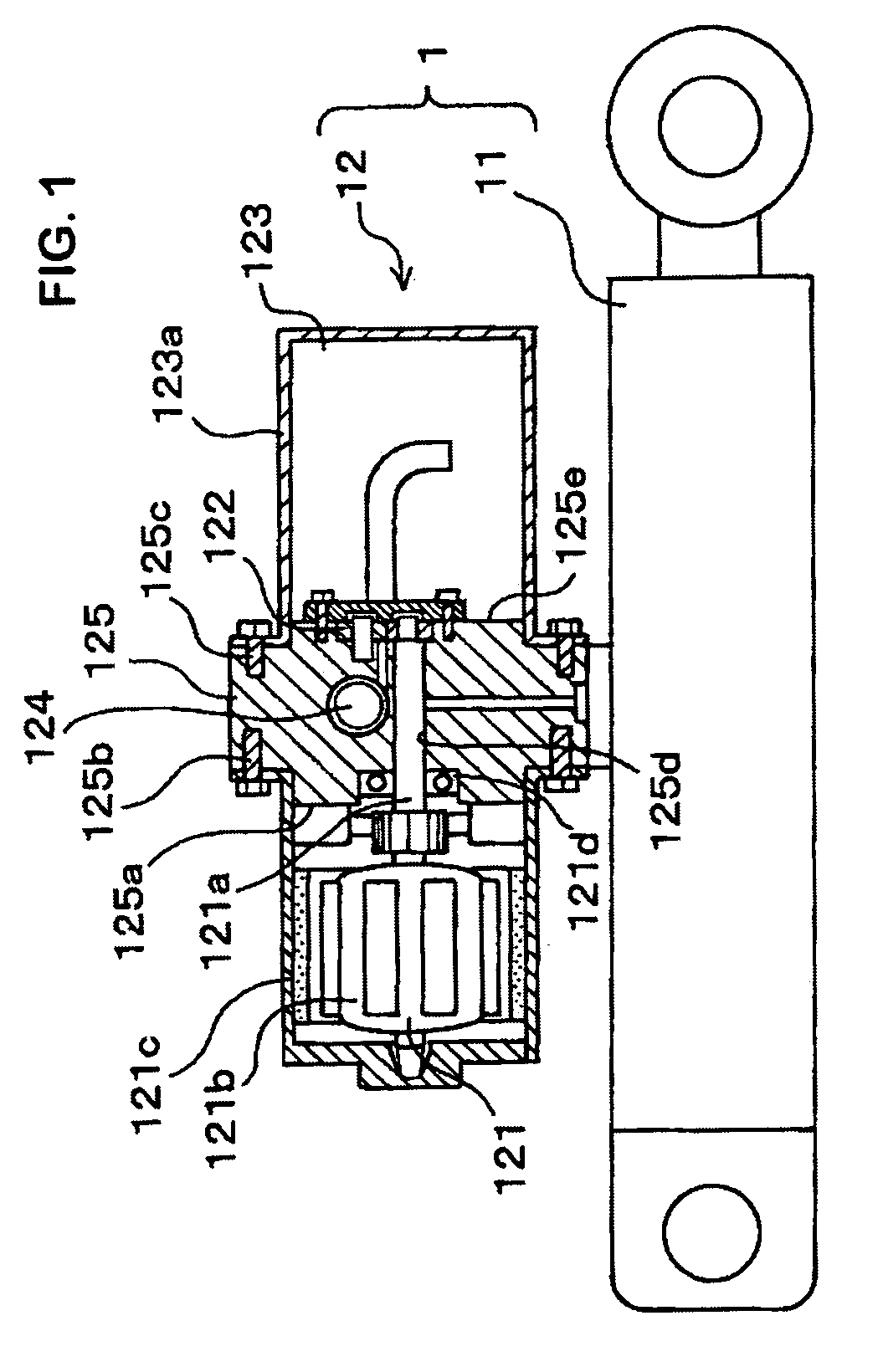
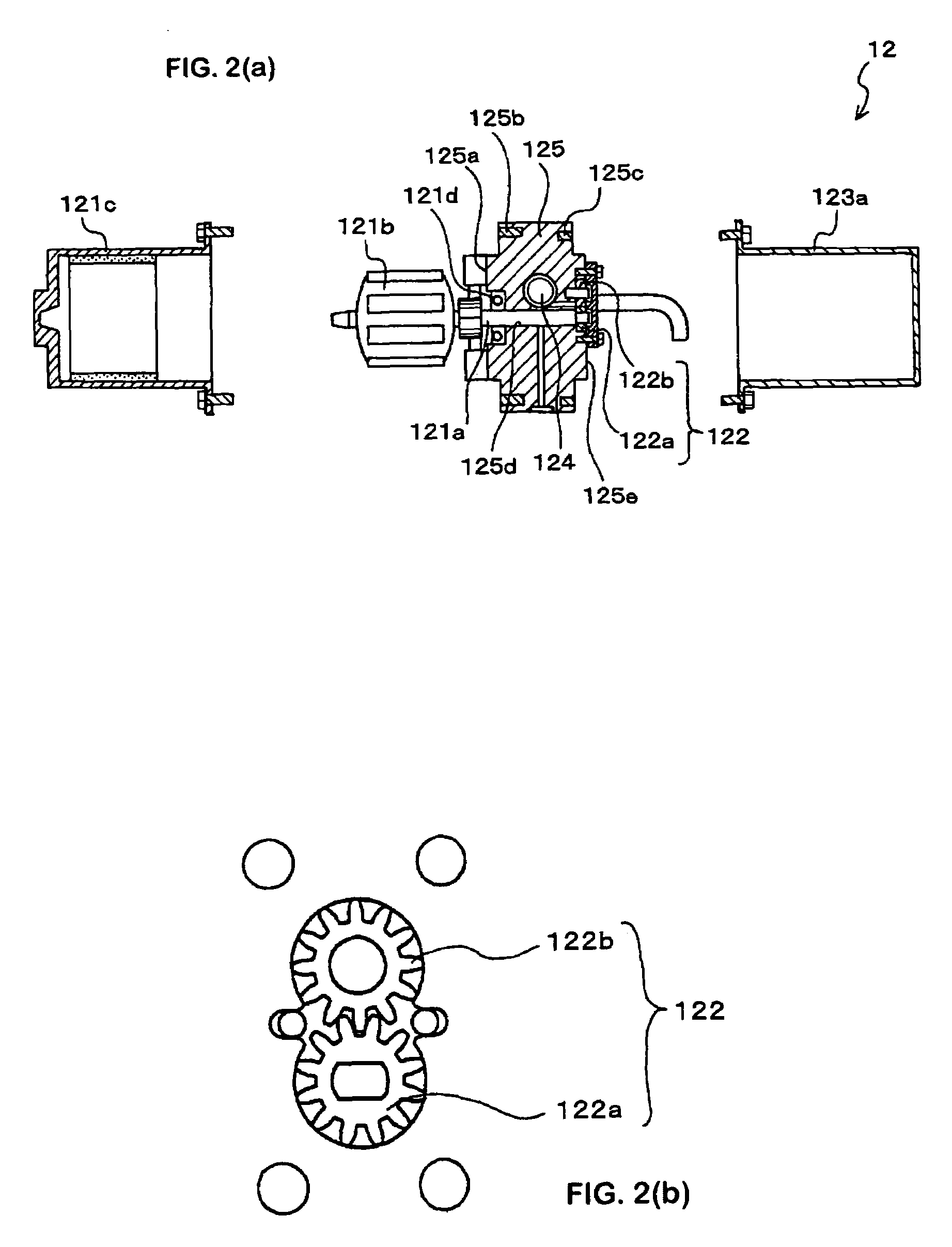
[0027]First, a hydraulic drive unit 1 of one example (Example 1) of the present invention is explained with reference to FIGS. 1, 2(a), and 2(b). FIG. 1 is a schematic view (in partial section) of the hydraulic drive unit of Example 1 of the present invention. FIG. 2(a) is an exploded view of a hydraulic controller which is a component of the hydraulic drive unit of Example 1, and FIG. 2(b) is a schematic plan view of a hydraulic pump portion shown in FIG. 2(a). The hydraulic drive unit 1 is made up of a hydraulic cylinder 11 that is one kind of an actuator, and a hydraulic controller 12 for expanding and contracting the hydraulic cylinder 11.

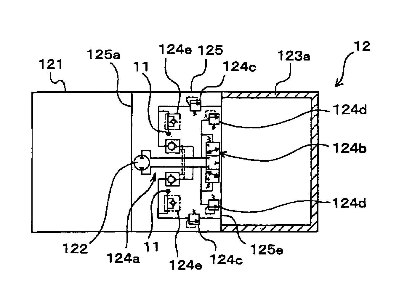
[0028]The hydraulic controller 12 includes an electric motor 121 capable of rotating in the normal and reverse directions, a hydraulic pump 122 for sending hydraulic oil under pressure in the normal and reverse directions by means of the rotation of the electric motor 121, an oil tank 123 for storing hydraulic oil in an enclosed space, valves 1...

example 2

[0035]Next, another example (Example 2) is explained with reference to FIGS. 3 and 4. Hereunder, the same reference characters are applied to portions explained already, the explanation thereof being omitted, and only different portions are explained.

[0036]In a hydraulic drive unit 2 of Example 2, a part of the housing 125 forms an electric motor cover body 125ab onto which is fitted a cap body 221c. Not only can the manpower required for assembly thereby be reduced but it is also possible to avoid damaging or misassembling components of the electric motor 121, which has been assembled to the housing 125, during the assembly process.

example 3

[0037]Next, still another example (Example 3) is explained with reference to FIGS. 5(a), (b), and (c) and FIG. 6. In Example 3, the position of the hydraulic pump 122 disposed in the housing 125 is changed, and an arrangement of the valves 124 that accommodates the change of the position of the hydraulic pump 122 is shown clearly.

[0038]Before Example 3 is explained, the features of the basic configuration of the valves 124 are explained. FIG. 6 is a hydraulic circuit diagram showing a basic configuration of a hydraulic drive unit 3. The hydraulic circuit shown in FIG. 6 is the same as the hydraulic circuits used in the devices of Example 1 and Example 2.

[0039]The valves 124 include, as basic components, an operate check valve 124a for controlling the flow of hydraulic oil in the normal and reverse directions between the hydraulic pump 122 and the hydraulic cylinder 11, and a switching valve 124b for controlling the flow of hydraulic oil in the normal and reverse directions between t...


PUM


Abstract

A hydraulic controller in which driving sound and the number of parts can be reduced, and a long service life can be realized, and a hydraulic drive unit provided with said hydraulic controller. The hydraulic controller for a hydraulic drive unit includes a housing that includes an electric motor housing configured to house an electric motor, an oil pump housing configured to house a hydraulic pump, and a valve housing configured to house valves are integrated together.

Description

BACKGROUND OF THE INVENTION[0001]The present invention relates to a hydraulic controller that includes a housing structure, and a hydraulic drive unit provided with the said hydraulic controller.[0002]A hydraulic drive unit that easily provides a driving force created by an oil pressure without laying hydraulic pipes if only an electric power source is present has been used, for example, for lifting work equipment of a special agricultural vehicle with respect to the cultivated ground, and in the future, the expansion of industrial application to many fields is anticipated.[0003]The hydraulic drive unit is broadly made up of an actuator (usually, a “hydraulic cylinder” is used) and a hydraulic controller for operating (expanding and contracting in the case of the hydraulic cylinder) the actuator. The hydraulic controller includes an electric motor capable of rotating in a normal and a reverse direction, a hydraulic pump for sending hydraulic oil under pressure in the normal and reve...

Claims


Application Information

Patent Timeline
Patent Type & Authority Patents(United States)
IPC IPC(8): F15B11/00F15B1/00
CPCF15B1/26F15B15/18F15B2211/20515F15B2211/7053F15B2211/3051F15B2211/613F15B2211/20561C02F1/40C02F2103/007E02B15/0857
Inventor SAKAI, YOSHITAKESATO, OSAMU
Owner KYB CORP
Why Eureka
Try Eureka