Automatic soap dispenser structure

a dispenser and automatic technology, applied in the direction of liquid/fluent solid measurement, volume metering, instruments, etc., can solve the problems of increasing the failure rate, increasing manufacturing and assembly costs, etc., and achieves the effect of improving the applicability of products, saving and smooth power, and fast power saving and smooth manner

Inactive Publication Date: 2007-10-16
LIN PO HUI
View PDF3 Cites 24 Cited by
  • Summary
  • Abstract
  • Description
  • Claims
  • Application Information

AI Technical Summary

Benefits of technology

[0009]Further, the rear panel corresponds to the press plate, and a latch surface, and a latch surface is protruded from the top of a lateral side, and a slightly recessive curved surface is disposed at the middle section and the lower section of an external side of the rear panel; such that when the press plate compresses a soap dispensing tube, the back plate of the press plate and the latch surface of the rear panel compress to close the upper section of the soap dispensing tube. Since the back plate is propped onto the top of the latch surface, so that the back plate becomes an axle center. If the press plate continues squeezing the soap dispensing tube, the back plate presses and squeezes the upper end of the soap dispensing tube to form a close status and also can maintain the previous pressing and squeezing effect without using additional squeezing force. The curvature and angle of the curved surface of the back plate and the curved surface of the press plate are skillfully designed in a way corresponding to each other to achieve a discharge cycle from the upper end to the lower end of the soap dispensing tube in a fast, power-saving and smooth manner, and then the design of a protruded curved surface of the press plate and a recessed curved surface of the rear panel compress the soap dispensing tube progressively downward. As a result, the liquid soap in the whole liquid supplying tube can be compressed and squeezed out in a single compressing routine, and thus producing a power-saving and smooth compressing effect and improving the applicability of the products.

Problems solved by technology

Although such arrangement can provide sufficient liquid soap for users in one operation, the increased number of control components makes the manufacturing and assembling cost much higher.
Further, although the prior art adopts the eccentric wheel, the prior art eccentric wheel is a component using a single force applying force, and some designs even require electric power for their applications which may increase the failure rate.

Method used


Image

  • Automatic soap dispenser structure
  • Automatic soap dispenser structure
  • Automatic soap dispenser structure

Examples


Embodiment Construction

[0030]To make it easier for our examiner to understand the objective of the invention, its structure, innovative features, and performance, we use a preferred embodiment together with the attached drawings for the detailed description of the invention.

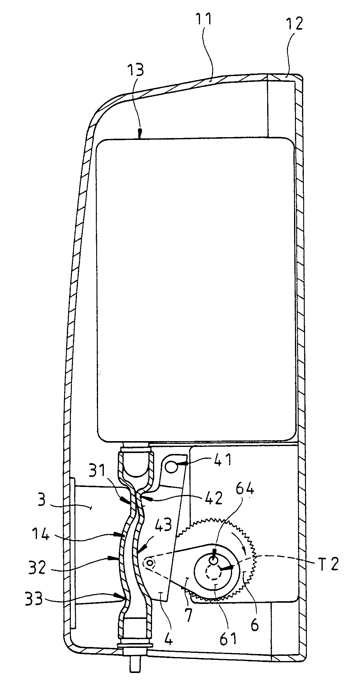
[0031]Please refer to FIG. 8, the soap dispensing tube 14 is installed between the rear panel 3 and the press plate 4, and a latch area which is an area where the dispensing tube is pinched off is defined between the latch surface 31 of the rear panel 3 and the back plate 42 of the press plate 4 and keeps an appropriate gap in between, so that the soap dispensing tube 14 is filled up with liquid soap which is in an idle status.

[0032]Referring to FIG. 9 for the liquid soap dispenser being activated by its sensor, the driving device drives the driving wheel 6 to rotate clockwise and synchronously drives the eccentric wheel 61 disposed on the driving wheel 6 clockwise, so that the eccentric wheel 61 pushes the link member 7, and an end of...


PUM


Abstract

An improved automatic soap dispenser structure includes a motor and a gear wheel module installed in a driving device of a soap dispenser to transmit a driving wheel and uses an eccentric wheel disposed on the driving wheel to produce an eccentric effect, characterized in that the eccentric wheel couples a link member, and the link member presses a press plate, such that when the press plate compresses a soap dispensing tube, a back plate of the press plate and a latch surface of a rear panel compress to close the upper section of the soap dispensing tube, and then the design of a protruded curved surface of the press plate and a recessed curved surface of the rear panel compress the soap dispensing tube progressively downward to produce a power-saving and smooth compressing effect.

Description

BACKGROUND OF THE INVENTION[0001]1. Field of the Invention[0002]This invention relates an improved automatic soap dispenser structure, and more particularly to an improved soap dispenser structure having an automatic sensor for providing liquid soap, and an appropriate quantity of the liquid soap can be squeezed out from the dispenser by a power-saving driving mechanism.[0003]2. Description of the Related Art[0004]The design of a soap dispenser is generally adopted and extensively used in public places for users to clean their hands, and the structure of a prior art soap dispenser usually includes a housing containing a bag of liquid soap, and one end of the bag is connected to an appropriate flexible soap dispensing tube. The soap dispensing tube adopts the design of a one-way check valve, and thus the liquid soap can be squeezed out in one direction and its backflow to the bag body can be prevented. The prior art automatic soap dispensers use a dry cell for supplying power to the ...

Claims


Application Information

Patent Timeline
Patent Type & Authority Patents(United States)
IPC IPC(8): B65D37/00
CPCA47K5/1215
Inventor LIN, PO-HUI
Owner LIN PO HUI
Why Eureka
Try Eureka