Blowing apparatus for refrigerators

a technology for refrigerators and blowing machines, which is applied in the direction of domestic cooling equipment, vessel parts, vessel construction, etc., can solve the problems of increased noise, increased flow loss, increased energy loss, etc., and achieves reduced energy consumption, minimizing flow loss, and noise reduction

Inactive Publication Date: 2007-10-16
LG ELECTRONICS INC
View PDF7 Cites 24 Cited by
  • Summary
  • Abstract
  • Description
  • Claims
  • Application Information

AI Technical Summary

Benefits of technology

[0015]Therefore, the present invention has been made in view of the above problems, and it is an object of the present invention to provide a blowing apparatus for refrigerators that is capable of blowing cool air using a centrifugal fan, instead of the conventional axial fan, to minimize flow loss, whereby energy consumption is reduced, noise is decreased, and thus the refrigerator is quietly operated.
[0022]In the blowing apparatus for refrigerators constructed as described above, the centrifugal fan is used instead of the axial fan to supply cool air. Consequently, the present invention has the effect of minimizing flow loss. As a result, energy consumption is reduced, noise is decreased, and thus the refrigerator is quietly operated.

Problems solved by technology

Consequently, the cool air flows in the axial direction due to the axial fan 14, which increases flow loss.
As a result, energy loss is increased, and noise is increased, which is an obstacle to designing more silent refrigerators.
As a result, flow loss, i.e., energy loss, is increased.
Consequently, flow loss is further increased, and noise is further increased.

Method used


Image

  • Blowing apparatus for refrigerators
  • Blowing apparatus for refrigerators
  • Blowing apparatus for refrigerators

Examples


Embodiment Construction

[0031]Now, a preferred embodiment of the present invention will be described in detail with reference to the accompanying drawings.

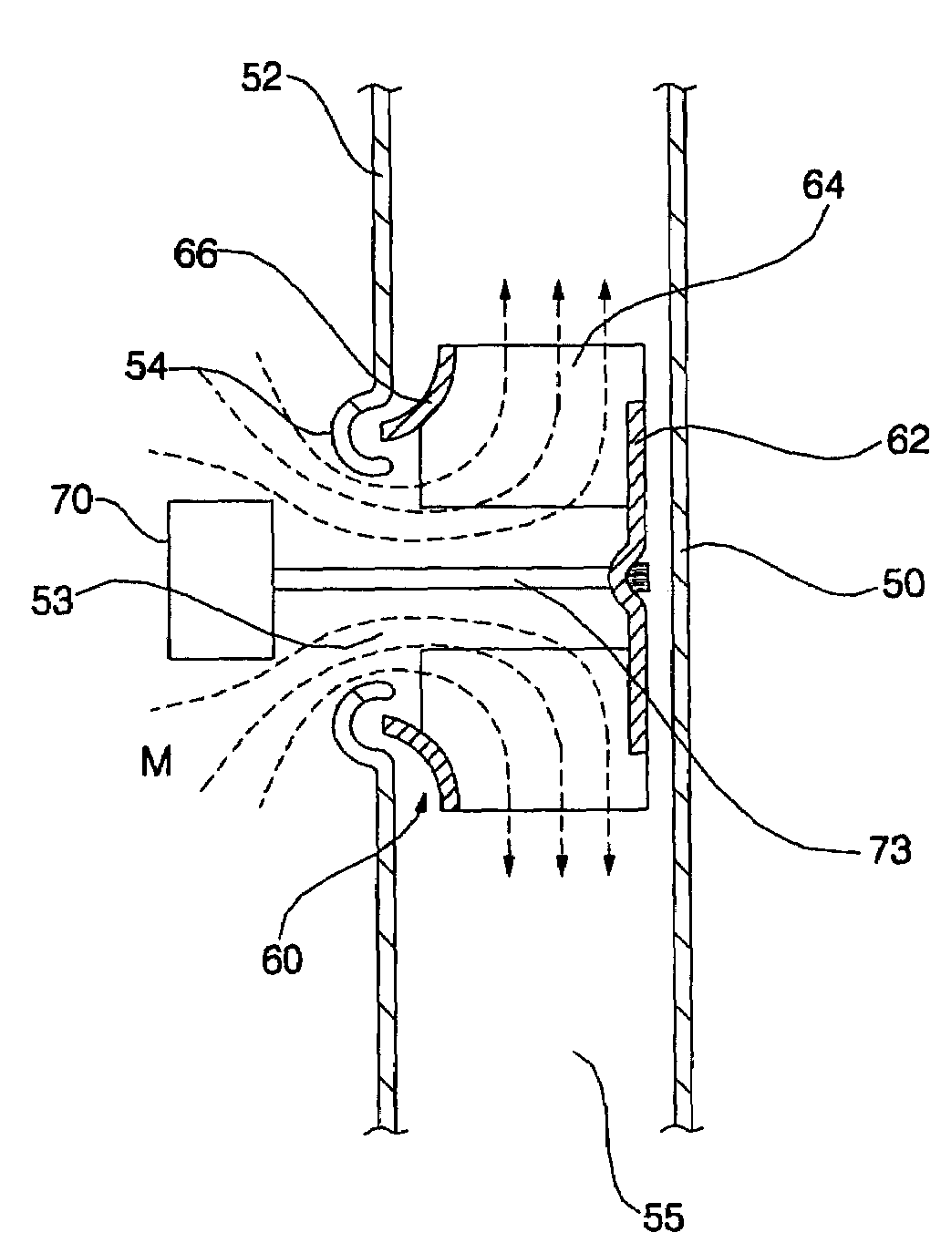
[0032]FIG. 3 is a sectional view showing a blowing apparatus according to a preferred embodiment of the present invention mounted in a refrigerator.

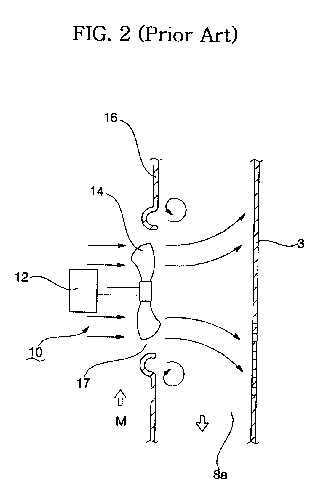
[0033]As shown in FIG. 3, a centrifugal fan 60 is used, instead of the conventional axial fan as described above, according to the present invention.

[0034]Specifically, a channel separation plate 52, which separates a cool air supply channel 55 from a machinery chamber M, is disposed in parallel with an inner case 50 of the refrigerator. At the channel separation plate 52 is formed a cool air introduction hole 53 where the centrifugal fan 60 is disposed.

[0035]The channel separation plate 52 is provided around the cool air introduction hole 53 with a bell-mouth part 54 having a convex section. Cool air introduced through the cool air introduction hole 53 is more efficiently introduced into the cool air supply ...


PUM


Abstract

Disclosed herein is a blowing apparatus for refrigerators. The blowing apparatus includes a centrifugal fan. The centrifugal fan comprises a hub plate connected to a shaft of the motor, a plurality of blades attached to the hub plate in the radial direction of the hub plate for forcing cool air to flow, and a ring-shaped shroud connected to ends of the blades. The ratio of the inner diameter of the centrifugal fan, formed through connection of the inner ends of the blades, to the outer diameter of the centrifugal fan, formed through connection of the outer ends of the blades, is 0.63±0.01. With the blowing apparatus for refrigerators according to the present invention, flow loss is minimized. Consequently, the present invention has the effect that energy consumption is reduced, noise is decreased, and thus the refrigerator is quietly operated.

Description

BACKGROUND OF THE INVENTION[0001]1. Field of the Invention[0002]The present invention relates to a blowing apparatus that is used to circulate cool air in a refrigerator, and more particularly to a blowing apparatus for refrigerators that is capable of blowing cool air using a centrifugal fan, instead of an axial fan, to reduce flow loss, whereby blowing noise is decreased, and power consumption is reduced.[0003]2. Description of the Related Art[0004]Generally, a refrigerator stores foodstuffs in a fresh state for a long time using cool air obtained by a refrigerating cycle. The cool air is used to cool and prevent decomposition of the foodstuffs.[0005]FIG. 1 is a sectional view showing the inner structure of a refrigerator with a conventional blowing apparatus mounted therein.[0006]As shown in FIG. 1, the refrigerator generally comprises an outer case 1 and an inner case 3. The inner case 3 is partitioned into an upper inner case section and a lower inner case section at a predeter...

Claims


Application Information

Patent Timeline
Patent Type & Authority Patents(United States)
IPC IPC(8): F04D29/28F25D17/06F04D29/42
CPCF04D29/282F04D29/4213F25D2317/0683F25D2317/0681F25D17/067F25D17/06
Inventor BAEK, SEUNG JOJUNG, YOUNG GYUKIM, CHANG JOON
Owner LG ELECTRONICS INC
Why Eureka
Try Eureka