Fluent control valve

a technology of control valve and fluid flow, which is applied in the direction of process and machine control, liquid engine with positive displacement, instruments, etc., can solve the problems of high rate of material ablation and erosion at the nozzle inlet, reducing the velocity and thrust obtained from the fuel, and affecting the operation of the valve. , to achieve the effect of reducing the cost of fabricating variable thrust rocket motors, reducing the cost of manufacturing, and reducing the variation of thrus

Inactive Publication Date: 2006-01-24
HOOSE KARL V
View PDF5 Cites 9 Cited by
  • Summary
  • Abstract
  • Description
  • Claims
  • Application Information

AI Technical Summary

Benefits of technology

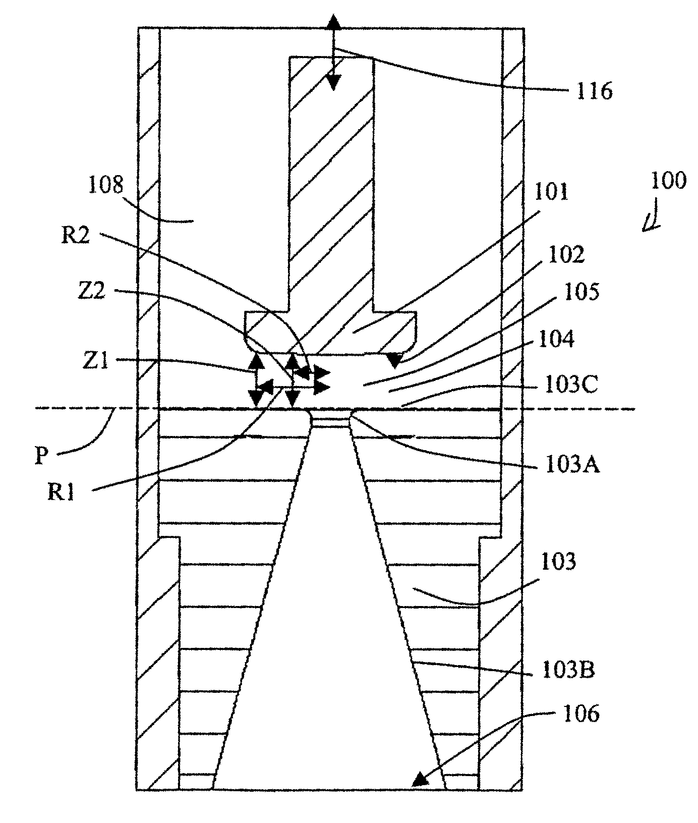
[0023]In rocket thruster applications, such as kinetic kill vehicles for missile defense, the FCV according to the invention, with its “hydrodynamic pintle” or HCS, eliminates thrust variations due to vibrations in the system. In the traditional design, a vibrating or off-axis pintle effects changes in the flow path that result in changes in the thrust and exacerbates the problem of ablation and erosion of the nozzle throat and pintle. By contrast, an off-axis or vibrating FCS according to the present invention does not affect the flowpath through the nozzle. Hence, the design requirements regarding rigidity and alignment of the vehicle structure can be relaxed, thereby reducing the cost of fabricating variable thrust rocket motors.
[0024]The FCV according to the invention has been studied in hydraulic applications and the following characteristics have been observed. The pressure drop across the FCV is much lower than in traditional pintle valves because of the absence of recirculation and flow separation. Thus, the FCV is much quieter in operation. Flow control is linear with opening of the FCV, down to essentially zero mass flow. Hence, the FCV provides a nearly infinite turn-down ratio and, consequently, serves as a very precise flow meter.
[0025]The response time of the FCV has been shown to be extremely fast in hydraulic applications. This is due to the very short stroke length required to move the FCV from full open to completely closed. Inherent in the design of a traditional pintle valve is that the pintle, to open the valve to the same degree, travels a greater distance than does a flat or nearly flat surface. That is, the stroke length of the FCV between full-open position and full-close position is shorter than the necessary stroke length in a traditional pintle valve between full-open and full-close positions. Minimizing the stroke length results in a quicker response time and also requires less power to actuate the FCV. Also contributing to the reduced power requirements to actuate the FCV is the fact that, because of the slight angle on the FCS relative to the surface of the nozzle, fluid at line pressure fills the space between the fluid control plate and nozzle plate when the FCV closes the exit nozzle entrance.
[0026]Further, the FCV according to the invention is extremely resistant to wear, even when the fluid is contaminated with solid particles. This further supports the findings of minimal turbulence and recirculation within the FCV. All of these observations are indications of superior performance potential for the FCV in supersonic fluid flow applications.
[0027]Experiments have been carried out with the FCV according to the invention under conditions of cold flow and hot flow, relevant to actual rocket thruster conditions, with regard to temperature and pressure, low pressure, subsonic and supersonic gas flow. The results show that the mass flow versus valve opening is linear with subsonic and supersonic flow throughout the FCV for constant plenum pressure conditions. Two-dimensional and three-dimensional CFD analysis has also been conducted on the FCV. In the case of supersonic flow, the FCV continues to show a linear relationship between mass flow and valve opening. A normal shock wave appears between the physical FCS and the nozzle inlet surface, whereby the opening of the FCV controls the height of the throat area, and therefore, of the normal shock. Hence, the valve opening controls the mass flow and, therefore, the overall thrust of the system. This provides the capability of precisely controlling the mass flow or thrust through the nozzle. In addition, the flow remains uniform throughout the nozzle, unlike in traditional plug or pintle type nozzles in which supersonic flow occurs near the nozzle walls and subsonic flow extends far down into the center of the nozzle.
[0028]Because the normal shock occurs between the FCS and the nozzle plate, the nozzle length actually extends 90 degree up around the radiused corner of the inlet onto the surface of the nozzle plate. This allows the overall physical length of the nozzle to be shortened, making a much more compact thruster.

Problems solved by technology

Also, if the flow is not properly aligned and turbulence or flow separation occurs, the separation will dissipate kinetic energy in the flow, thus reducing the velocity and the amount of thrust obtained from the fuel.
Several disadvantages are inherent with the use of a 45-degree pintle in applications of supersonic fluid flow.
This first area contributes largely to the high heat flux in the nozzle and leads to a high rate of material ablation and erosion at the nozzle inlet.
This area is particularly problematic due to the high surface to volume ratio of material at the tip of the pintle to the amount of heat being transferred from the fluid to the pintle.
Because of this, the material at the tip rapidly melts away, thereby drastically changing the geometry of the flow control surface.
Any change in geometry results in a rapid deterioration of thruster performance.
Although rhenium can minimize the material ablation in the valve, it has disadvantages in that it is an extremely heavy material and also very expensive and difficult to obtain.
Any misalignment of the pintle leads to significant performance degradation.
The gas under the higher pressure will tend to flow into areas of lower pressure, causing secondary flow fields with their inherent energy losses due to additional heating and separation.
Furthermore, vibrational excitations emanating from the structure / vehicle may also cause a misalignment of the pintle, which, if the pintle and nozzle touch, may result in catastrophic failure of the valve.
The fact that the 45-degree pintle is a rigid mass situated in the flow path is a further disadvantage.
The fluid flow is forced along the boundary surface of the pintle as it passes through the throat, resulting in loss of kinetic energy in the flow due to friction against the boundary surface.
Also, gaseous fluids are often contaminated with solid particles.
Due to the severe weight and space constraints that are typically applied to the construction of vehicles in a missile system, operating a thruster valve in pulse-mode has disadvantages that affect accuracy and cost of the missile system.
For example, the pulsing produces significant structural vibrations that severely hamper the operation and performance of the high-precision components in the guidance and seeker systems on the vehicle.
Consequently, the seeker housing has to be vibrationally isolated from the body of the vehicle in order to maintain proper performance, and this is technically a difficult and costly task.
A severe disadvantage of the Feild device for supersonic flow applications is that it teaches a straight-edge nozzle inlet (orifice), that is, a 90° drop-off at the edge of the orifice.
The rate of expansion is uncontrolled with such a sudden drop-off, making the device unsuitable for use with supersonic fluid flow.

Method used


Image

  • Fluent control valve
  • Fluent control valve
  • Fluent control valve

Examples


Embodiment Construction

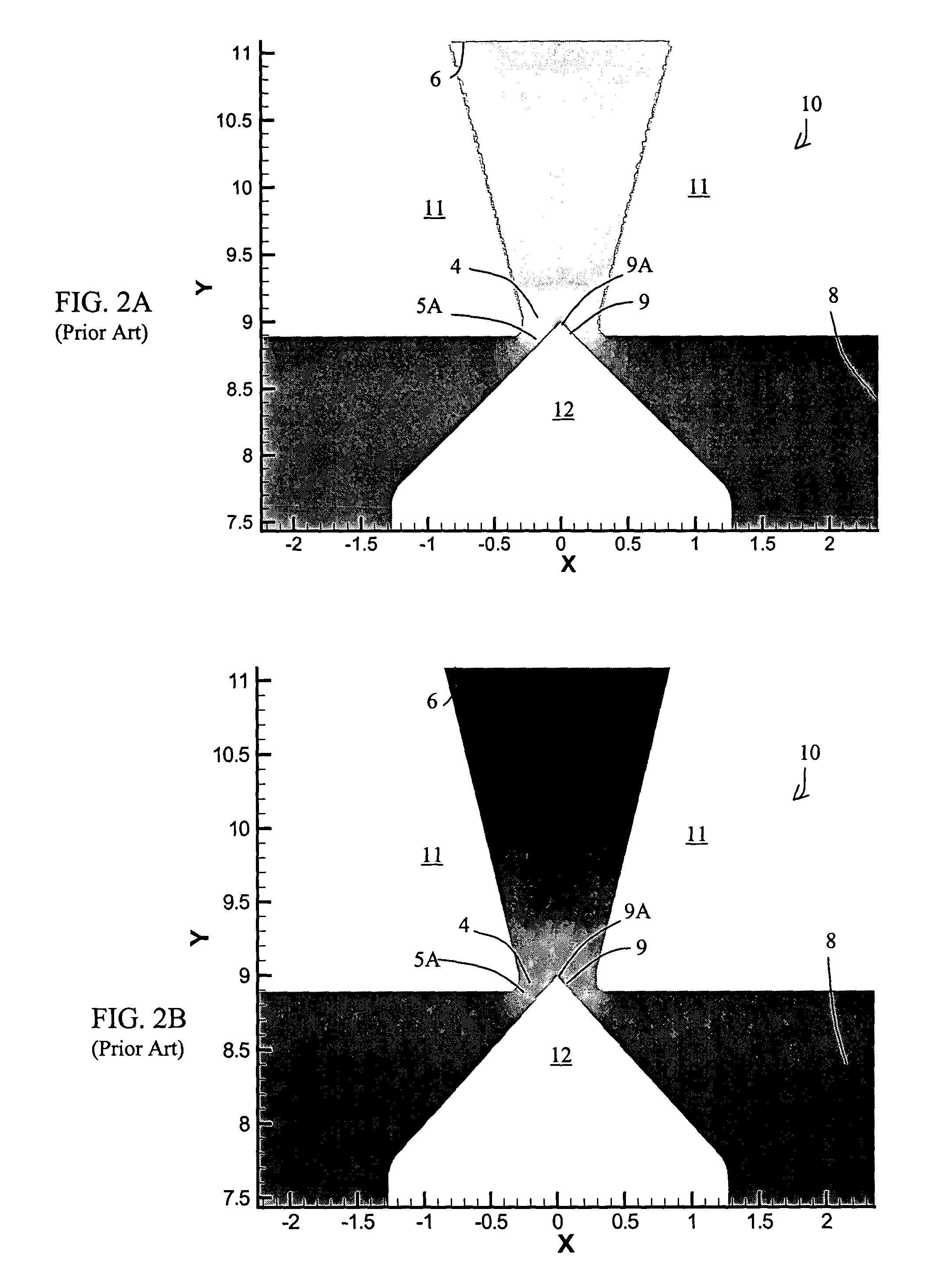
[0044]The computational flow dynamic (CFD) illustrations submitted with this application are color graphs, whereby the various temperatures, pressures, and Mach conditions are indicated by colors and color gradations. In all illustrations, the highest values are indicated by the color red and the lowest values by the color blue. A normal shock wave is generally indicated by the color yellow.

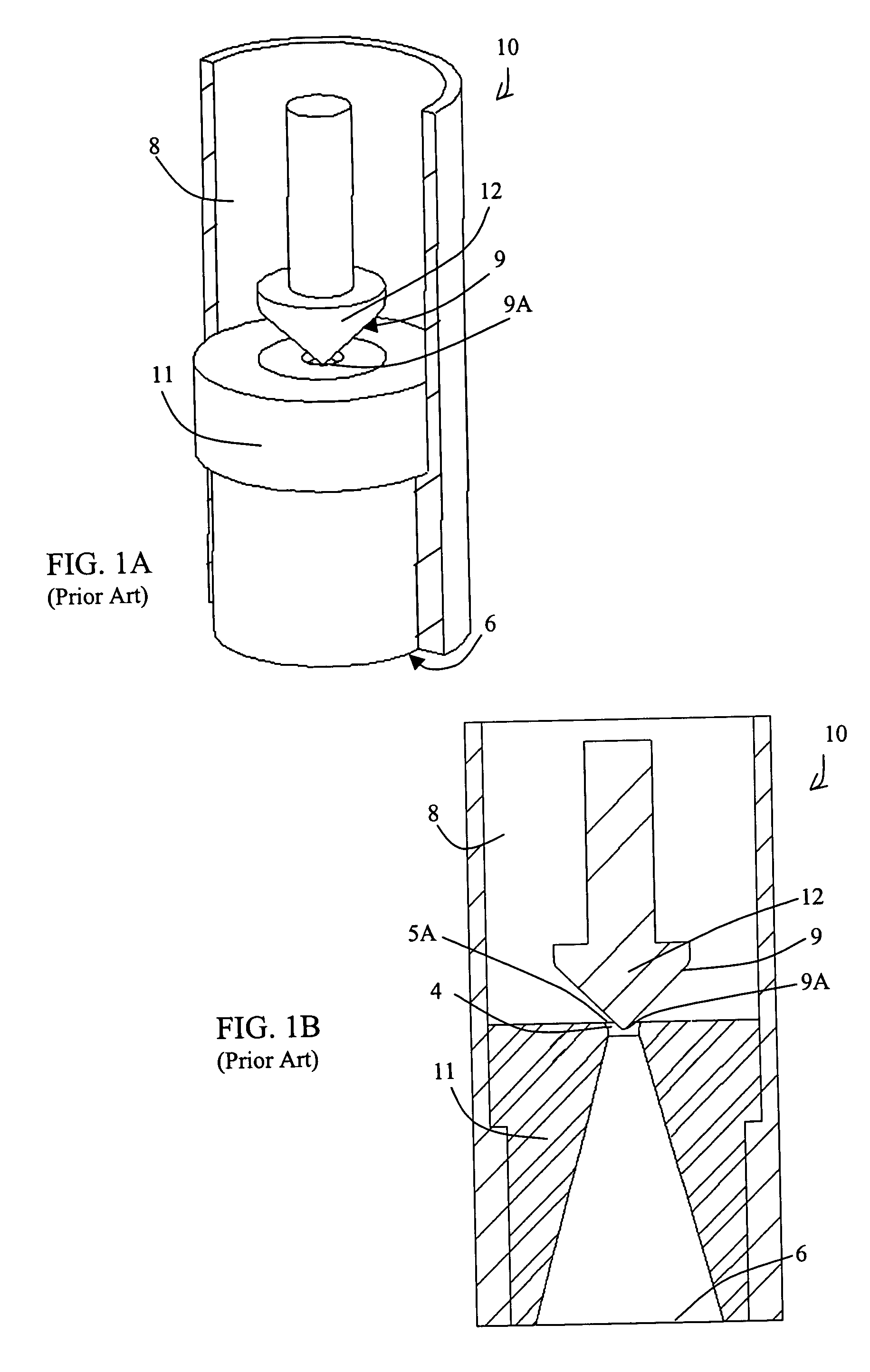
[0045]FIGS. 1A and 1B illustrate a traditional 45-degree valve 10 with a nozzle 11, a 45-degree pintle 12, a valve plenum 8. The valve is traditionally set into a housing which locates the nozzle and pintle into position. The nozzle 11 has an upper surface 11A, a nozzle inlet 4 and a nozzle exit 6, and the pintle 12 has a tip 9A. The portion of the pintle 12 that extends into the fluid flow provides a fluid control surface 9 that redirects the flow direction toward the nozzle exit 6. A fluid dynamic throat 5A forms between the nozzle inlet 4 and the pintle 12 as the valve 10 opens.

[0046]FIG. 2A a...


PUM


Abstract

A continuously variable fluent control valve for controlling supersonic flow of gas. The valve has an upper plate with a very slightly angled physical control surface and a lower plate with a physical nozzle inlet. As the valve opens and closes during supersonic flow, a hydrodynamic pintle forms in the nozzle inlet just below the physical control surface. The hydrodynamic pintle provides a fluid control surface for redirecting flow from horizontal fllow to vertical flow through the nozzle and, depending on the expansion needs of the supersonic flow, the hydrodynamic pintle changes shape, expanding or shrinking in the axial direction of the valve. Because of the nearly flat physical control surface of the upper plate, matieral ablation is significantly reduced. The fluid-fluid boundary between the hydrodynamic pintle and the supersonic flow produces a flow through the nozzle with little or no recirculation.

Description

[0001]This utility patent application claims priority under 35 U.S.C. 119(e) from application 60 / 413,208, filed on Sep. 24, 2002, the subject matter of which is herein incorporated by reference.BACKGROUND INFORMATION[0002]1. Field of the Invention[0003]The invention relates to the field of fluid control valves. More particularly, the invention relates to fluid control valves for regulating supersonic gas flow.[0004]2. Description of the Prior Art[0005]The purpose of a supersonic flow valve, for example, a thruster valve in a rocket booster or divert thruster, is to align the momentum of fluid flow with the direction of the desired thrust. During optimal performance, all the velocity components of the fluid flow are aligned with the direction of flight or thrust. Vectored flow, that is, flow that has velocity components at an angle relative to the direction of flight, will produce a vectored thrust. Also, if the flow is not properly aligned and turbulence or flow separation occurs, t...

Claims


Application Information

Patent Timeline
Patent Type & Authority Patents(United States)
IPC IPC(8): F04B49/00
CPCF02K9/80F02K9/978F02K9/88Y10T137/2605
Inventor HOOSE, KARL V.
Owner HOOSE KARL V
Why Eureka
Try Eureka