Progressive staged flow to precompress the pump internal volume/volumes to be displaced

a staged flow and pump technology, applied in the direction of machines/engines, rotary/oscillating piston pump components, liquid fuel engines, etc., can solve the problems of cavitation wear and noisy operation

Inactive Publication Date: 2009-11-17
NIEMIEC ALBIN J
View PDF5 Cites 9 Cited by
  • Summary
  • Abstract
  • Description
  • Claims
  • Application Information

AI Technical Summary

Benefits of technology

[0006]The present invention consists of providing pressurized flow through multistaged restrictive openings to precompress the volume to be displaced. With multistaged orificing the precompressive flow contains considerably less outgassing, which results in quieter operation and reduced erosion wear.
[0010]One of the principle objectives of the present invention is to provide a rotary flow restrictive feature in vane pumps that reduces the outgassing during precompression. The multistaged restrictions in the interfaced porting reduces the amount of outgassing in the fluid volume to be displaced during precompression.
[0015]The radial porting in the rotor segments, the varied opening of the axial ports in the rotor registering with the access port in the valve faces, and the connecting passage provide the multistaged restrictions for reducing the outgassing associated with throttled pressurized flow.
[0026]A partial vacuum is created in the pump inlet as the rotating gears unmesh. Fluid is drawn into the intertooth spaces and carried by the rotating gears to the region where the gears mesh and the entrapped fluid volumes are displaced. The pump timing on the side plates include grooves that originate at the discharge and surround the periphery above the minor diameter of both gears. This groove is terminated short of the inlet zone to allow for a minimum one tooth seal. This design strategy provides a radial hydrostatic pressure force to prevent the engaged gear teeth from mechanically separating because of the pressure angle of the meshed tooth engagement. Also, the wrap-around pressure distribution reduces the net radial hydrostatic pressure force supported by the journal bearings.

Problems solved by technology

When the pump intake volume is not completely filled the metering groove provide the single restrictive orifice for the displaced fluid to suddenly return and complete the pump filling; this rapid reversed flow is associated with increased outgassing and turbulence that produce cavitation wear and noisy operation.

Method used


Image

  • Progressive staged flow to precompress the pump internal volume/volumes to be displaced
  • Progressive staged flow to precompress the pump internal volume/volumes to be displaced
  • Progressive staged flow to precompress the pump internal volume/volumes to be displaced

Examples


Embodiment Construction

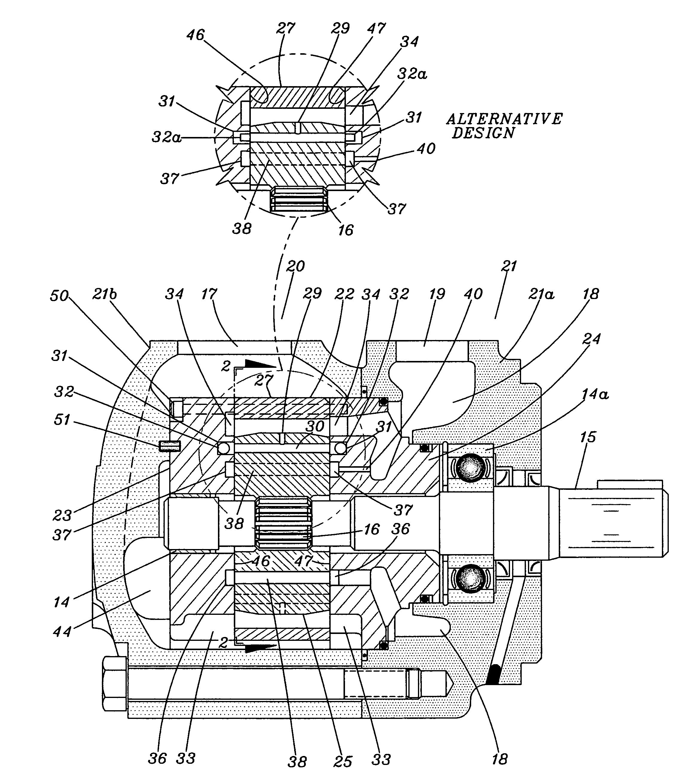
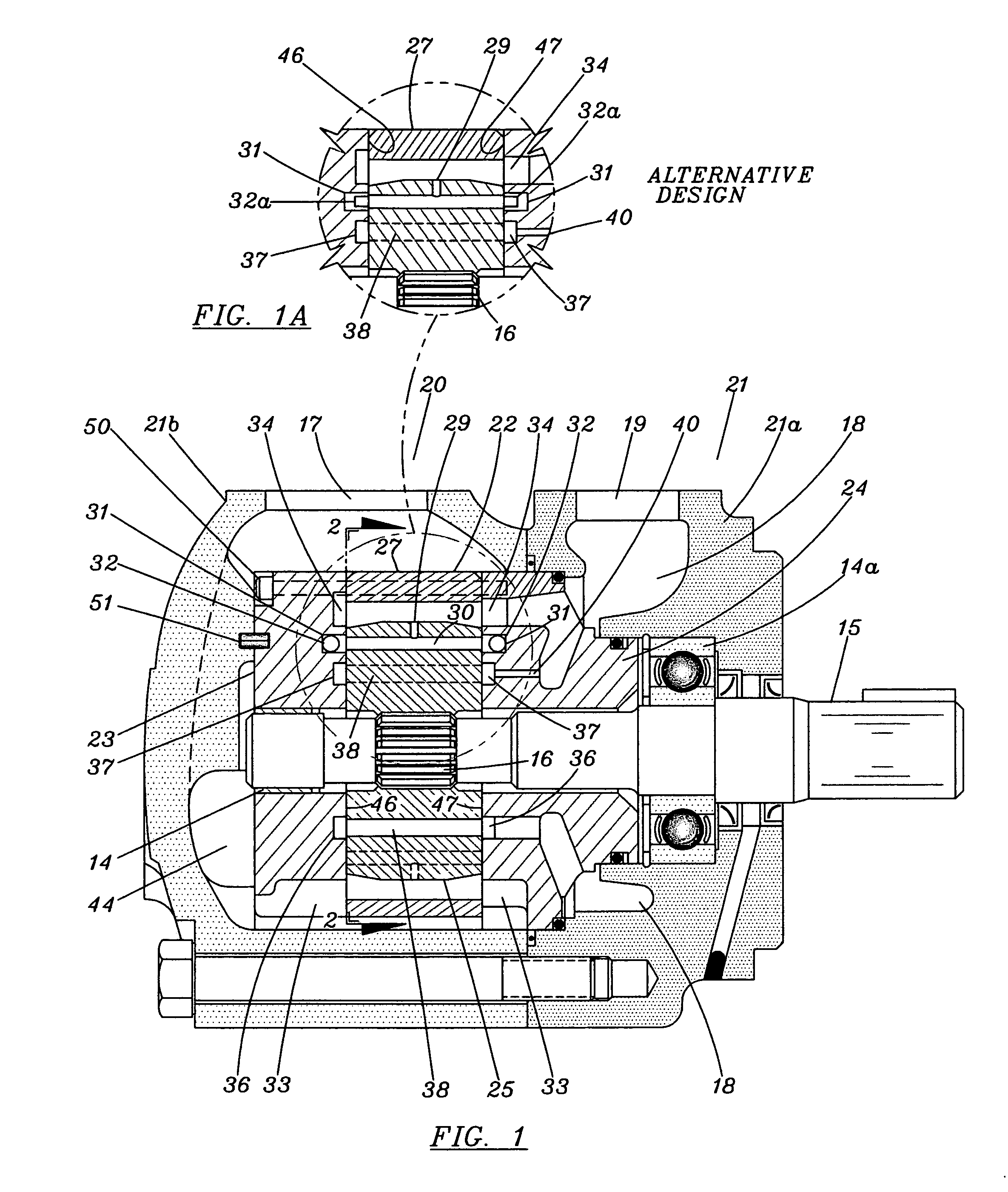
[0044]Referring to FIGS. 1, 2 and 3, therein is shown a rotary sliding vane pump 20 comprising of a housing 21 and a cartridge subassembly 22. The housing 21 comprises of a body 21a and cover 21b. The cartridge 22 includes a cam ring 27 sandwiched between support plates side 23 and 24. The body 21a provides an outlet connection port 19 which is directly connected to a discharge chamber 18 formed between the body 21a and the support plate 24. The pair of discharge ports 34 in the support plate 24. The pair of discharge ports 34 in the support plate 24 open into the discharge chamber 18. The cover 21b provides a supply connection port 17 leading into a pair of fluid inlet openings 33 formed in support plates 23 and 24.

[0045]A rotor 25 is rotatably mounted within cam ring 27 on the spline 16 of shaft 15 which is rotatably mounted within bearing 14 in support plate 23 and a ball bearing 14a mounted in body 21a.

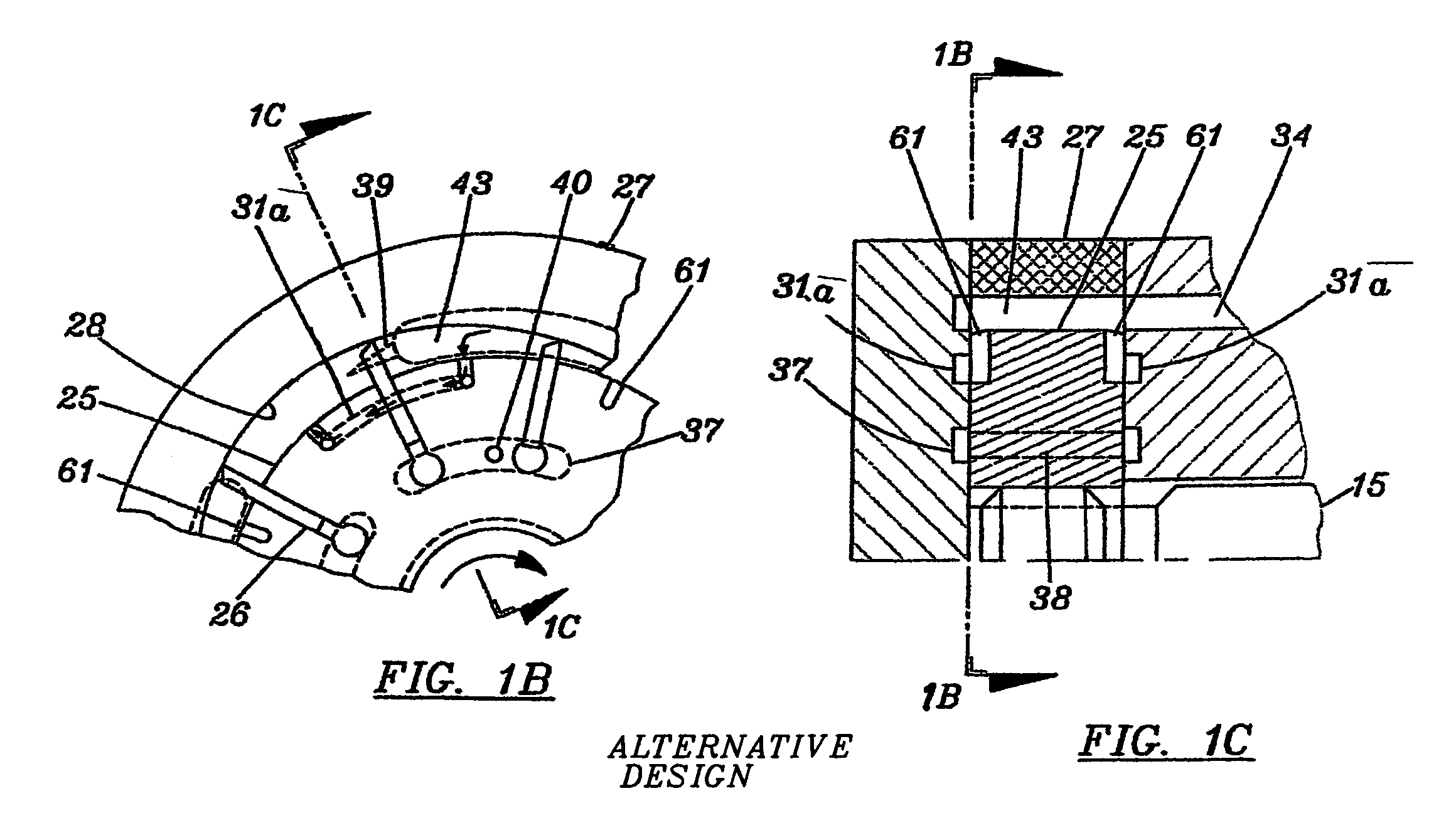
[0046]Cam ring 27 has an internal contour 28 which is substantially oval in ...


PUM


Abstract

Besides the conventional pump timing in rotary hydraulic devices, a series of constant and variable restrictions have been applied to condition the pressurized flow used to internally precompress the volume or volumes to be displaced. This multiple staged orifices feature reduces the outgassing associated with the pressurized flow passing through a single restriction, such as a metering groove. The pressurization of the outgassed fluid will cause noise and erosive wear of the pump internal containment surfaces.

Description

[0001]The present invention is directed to rotary hydraulic devices capable of functioning as pumps, motors, flow dividers, pressure intensifier and the like, and more particularly to vane and gear pumps.BACKGROUND AND OBJECTS OF INVENTION[0002]Most of the conventional positive displacement rotary pumps apply single stage pressurized flow to hydrostatically precompress the internal fluid volume to be displaced. The throttled pressure of a single staged flow contributes to the release of dissolved air into the internal pump volume to be displaced. The entrained air bubbles are imploded during the pump precompression and discharge cycles. Noisy operation and erosive wear are encountered.[0003]To reduce the outgassing in the pressurized flow encountered in the precompression cycle, a series of constant and variable restrictions are located in the flow passage to alter the throttled pressure.[0004]The application of the progressive staged flow for precompressing the internal pump volume...

Claims


Application Information

Patent Timeline
Patent Type & Authority Patents(United States)
IPC IPC(8): F04C15/00F04C2/00
CPCF04C15/062F04C2/10F04C2/3441F04C2/14
Inventor NIEMIEC, ALBIN J.
Owner NIEMIEC ALBIN J
Why Eureka
Try Eureka