
Device and a method for filtering a fluid

a fluid filtering and fluid technology, applied in the direction of filtration separation, sedimentation settling tanks, separation processes, etc., can solve the problem that both of these filtering devices are relatively expensive to produce, and achieve the effect of simple operation, inexpensive and effective devices, and simple production

Inactive Publication Date: 2007-10-16
SHELL TECH VENTURES FUND 1
View PDF20 Cites 7 Cited by
  • Summary
  • Abstract
  • Description
  • Claims
  • Application Information

AI Technical Summary

Benefits of technology

[0011]Thus, there is an increasing need for a simple, inexpensive and effective device for filtering a fluid. Therefore, it is an object of the present invention to provide a device for filtering a fluid, which device is effective in filtering the fluid, is inexpensive to produce and is simple to operate.
[0039]It is also within the scope of the present invention to provide a method of filtering a fluid. Thus, according to a third aspect of the present invention, there is provided a method for filtering fluids through a device or a system according to any of the embodiments of the first and the second aspects of the present invention, the method including: passing the fluid through the device, compressing the fibers in a radial direction at a location along the flexible membrane, so as to reduce the total cross-sectional area of the fibers and thereby the cross-sectional area of the flow-passages, whereby the cross-sectional areas of the flowpassages gradually decrease towards the location, and maintaining the pressure on the fibers while passing the fluid through the flowpassages.

Problems solved by technology

Both of these filtering devices are relatively expensive to produce.

Method used


Image

  • Device and a method for filtering a fluid
  • Device and a method for filtering a fluid
  • Device and a method for filtering a fluid

Examples


Embodiment Construction

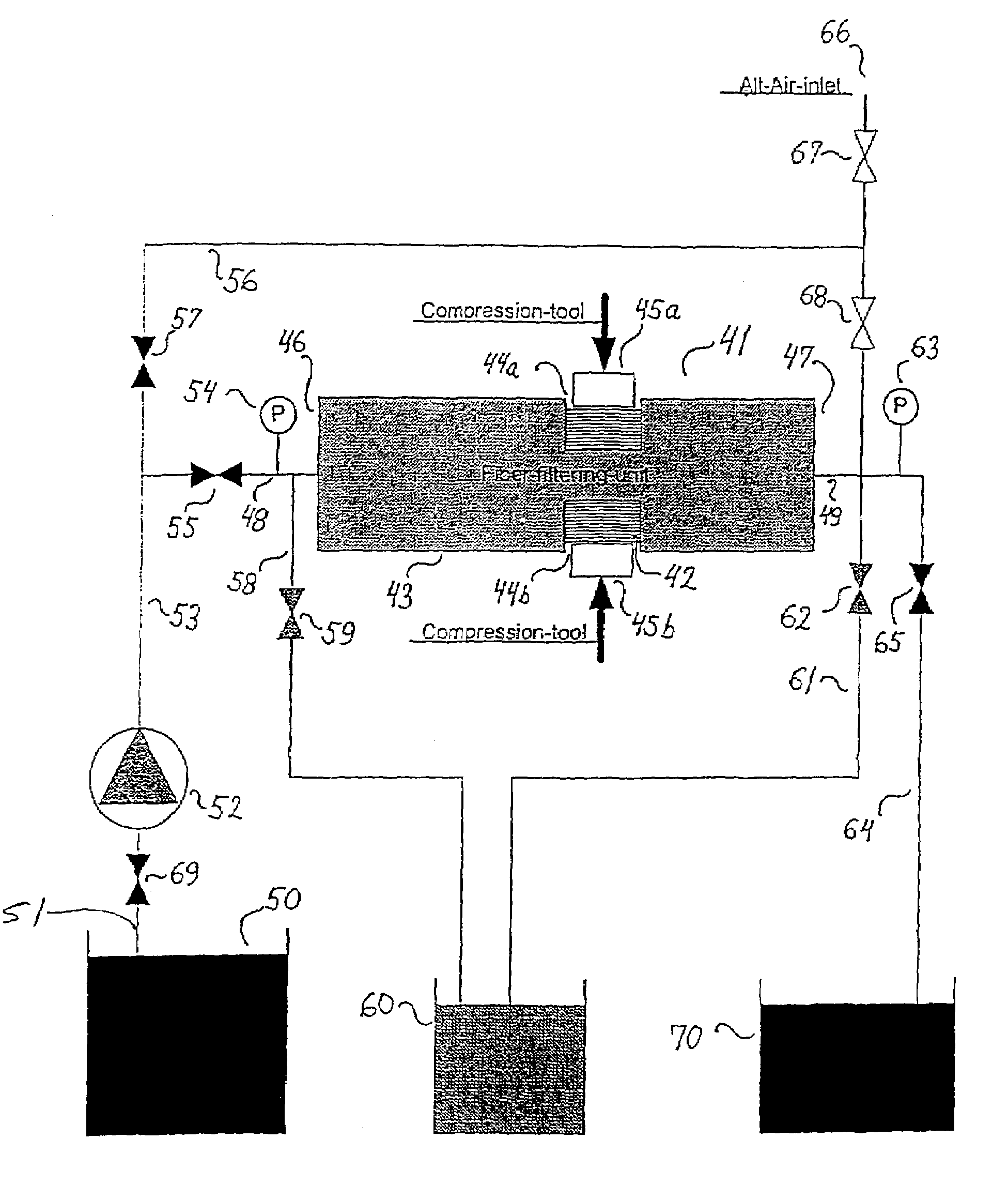
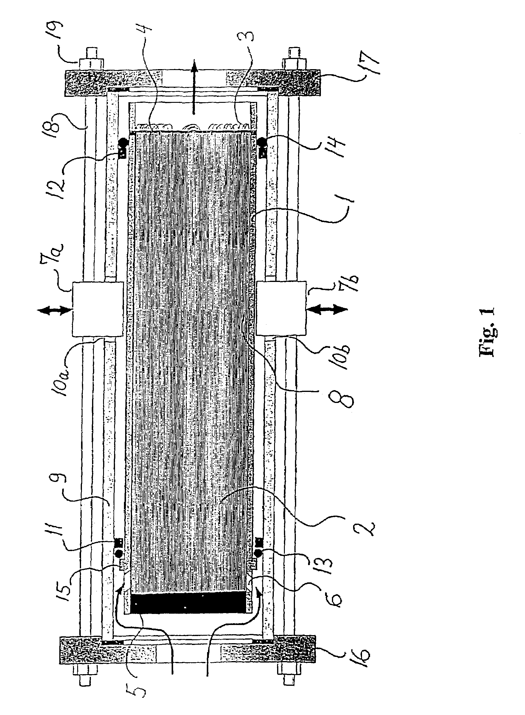
[0047]In FIG. 1 is shown a longitudinal section view of an embodiment of a filtering device according to the present invention. The filtering device of FIG. 1 comprises a fiber housing 1 having the form of a tube. Here, the fiber housing 1 is made of a flexible, watertight material in all the housing length, whereby the fiber housing is formed as a flexible membrane surrounding a bundle of fibers 2. The bundle of fibers 2 comprises a plurality of fibers extending longitudinally in the fiber housing 1.

[0048]In the illustrated embodiment the fibers are bent to thereby obtain a bundle of bent or folded fibers 2 having a length being about half the length of the non-bent fibers. The bent end of the fibers is arranged in an outlet end 3 of the fiber housing 1. Here the fibers may be bent around a cross 4 secured to the fiber housing 1 by gluing with, for example, epoxy. The free ends of the fibers are arranged in an inlet end 5 of the fiber housing 1. Here, it is preferred that the fiber...


PUM

PropertyMeasurementUnit
distanceaaaaaaaaaa
distanceaaaaaaaaaa
distanceaaaaaaaaaa

Abstract

A device for filtering a fluid includes a fiber housing having an inlet end with at least one inlet and an outlet end with at least one outlet. The fiber housing surrounds and defines an outer bound for a plurality of fibers extending longitudinally in the fiber housing between the inlet end and the outlet end, whereby longitudinally extending interspaces is provided between the fibers, with the interspaces defining a plurality of flow passages for the fluid. At least part of the fiber housing is formed of a flexible membrane surrounding the fibers, and a compression tool is provided for creating a pressure on an outer surface of the flexible membrane thereby compressing the fibers in a radial direction at least one location along the length of the fibers.

Description

[0001]This application is a continuation of PCT / EP01 / 10707, filed Sep. 17, 2001, which designated the United States and was published in English under PCT Article 21(2) on Mar. 28, 2002 as International Publication Number WO 02 / 24306 A1. PCT / EP01 / 10707 claims priority to U.S. application No. 60 / 233,658 and British Application 0022950.0, both filed Sep. 19, 2000. The entire contents of the three applications are incorporated herein by reference.BACKGROUND OF THE INVENTION[0002]1. Field of the Invention[0003]The present invention relates to a device and a method for filtering a fluid. More particularly the present invention relates to a device for filtering a fluid wherein a plurality of fibers extend longitudinally in the direction of the fluid flow during filtration of the fluid.[0004]2. Description of the Related Art[0005]U.S. Pat. No. 4,219,420 discloses an arrangement for filtering a contaminated fluid or medium. According to the disclosure of this patent a plurality of fiber bun...

Claims


Application Information

Patent Timeline
Patent Type & Authority Patents(United States)
IPC IPC(8): B01D37/00B01D29/00B01D24/00B01D29/60B01D29/66B01D35/10B01D39/04
CPCB01D35/10B01D2201/186B01D2201/184
Inventor BOYE, BO
Owner SHELL TECH VENTURES FUND 1
Learn More