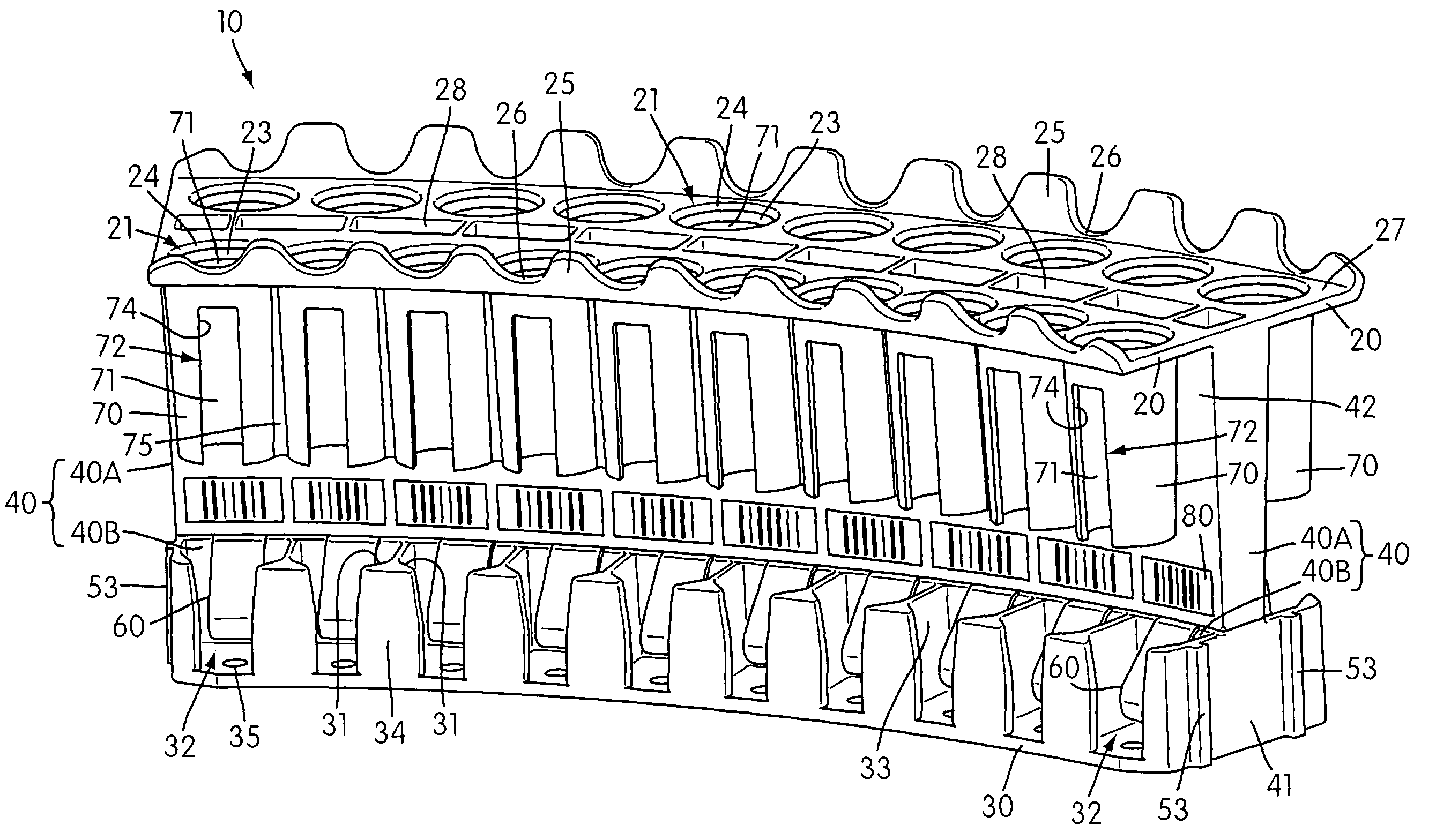
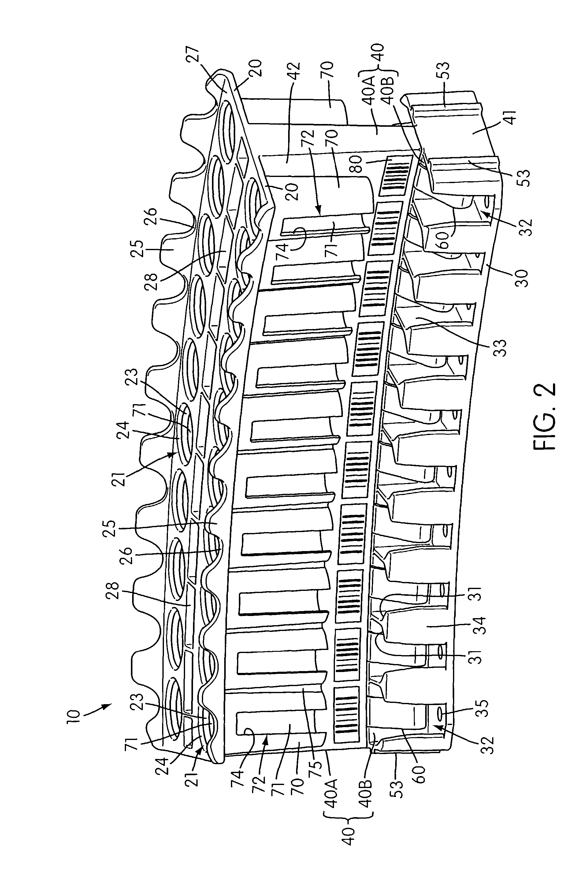
[0010]In a preferred embodiment, the top wall of the sample carrier extends laterally in both directions from the support wall and includes a series of aligned openings along opposite sides of the support wall. The openings are preferably circular in geometry, and the size of the openings may be the same or different to accommodate sample tubes having caps of equal or different diameters. Preferably, the top wall is chamfered about the periphery of each opening to facilitate
insertion of the sample tubes into the sample tube holding areas.
[0012]In still another embodiment of the present invention, the top wall has upwardly flared edges to facilitate handling of the sample carrier and to minimize user contact with the sample tubes. In a preferred embodiment, the edges further include a series of recesses. Pairs of opposed recesses are positioned adjacent openings in the top wall to accommodate
insertion and removal of sample tubes from and into the sample tube holding areas.
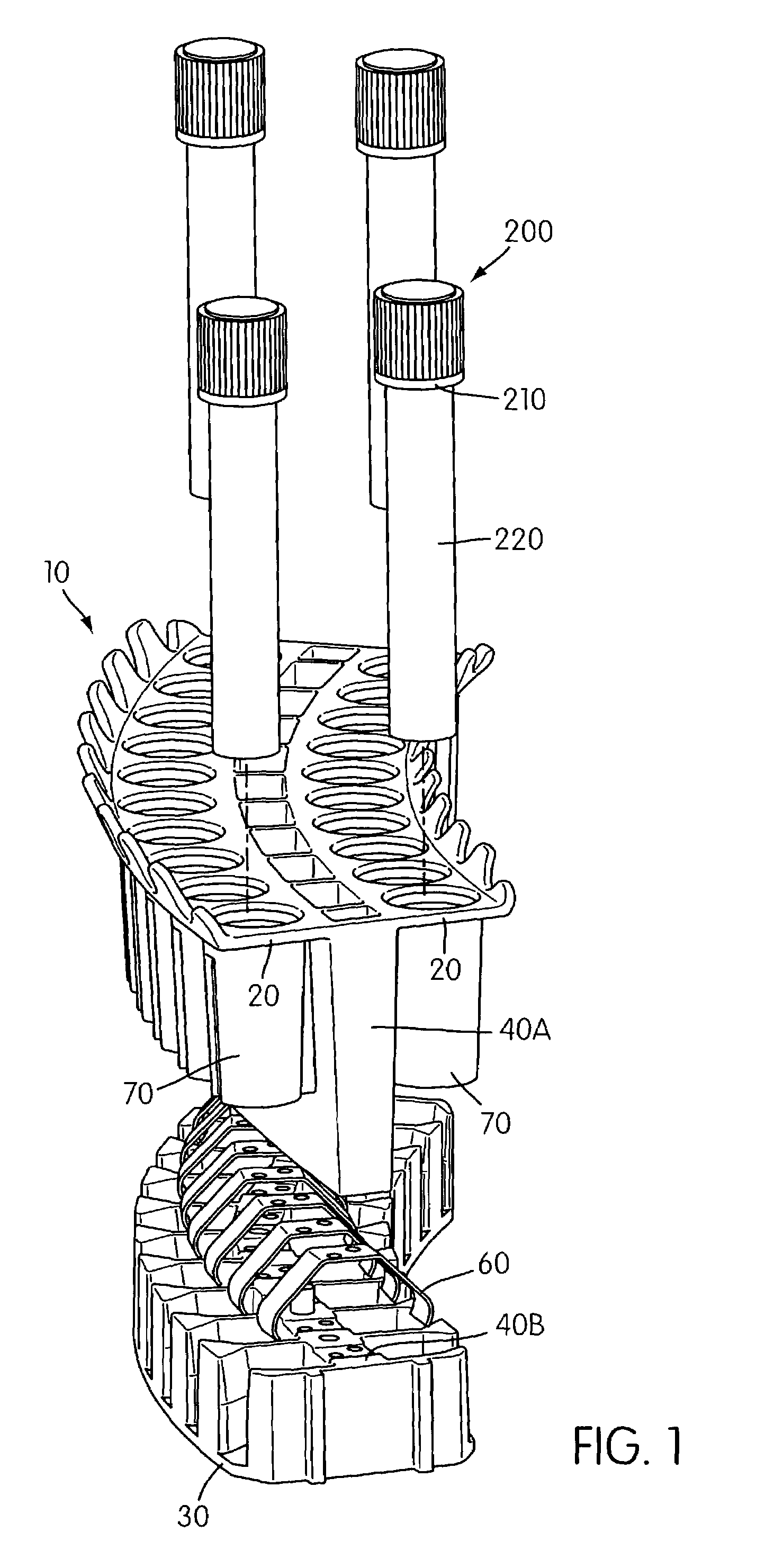
[0015]In still another embodiment of the present invention, the inner surfaces of the openings and sleeves are dimensioned so that penetrable cap components of the sample tubes are centered within the openings when the sample tubes are inserted into the sample tube holding areas. Centering of the caps prior to piercing with a robotic pipettor can help to limit the forces required to pierce the caps and can provide for more accurate pipetting. In a preferred embodiment, the sample tubes are centered for cap piercing to within about 0.125 inches (3.18 mm) from the longitudinal axis of a top surface of the cap component of the sample tube and more preferably to within about 0.1 inches (2.54 mm).
[0017]In a further embodiment of the present invention, a drip shield is provided which protects the contents of sample tubes held by a sample carrier from fluid
contamination, especially hanging droplets which may be dislodged from a robotic pipettor during an automated sampling procedure. The drip shield includes a cover plate which may have an
arcuate shape conforming to the
arcuate shape of the preferred sample carriers.
[0018]The cover plate of the drip shield includes one or more through-holes, where each through-hole is configured and arranged to provide non-interfering, vertical passage of an aligned
pipette tip therethrough. The through-holes are sized to permit access to the contents of only one sample tube at a time, where the sample tubes being accessed are present in a sample carrier positioned beneath the cover plate. In a preferred embodiment, the
diameter of each through-hole is the same as or smaller than the
greatest diameter of any sample tube carried by the sample carrier to minimize opportunities for contaminating the sample carrier and its contents. A top surface of the cover plate may be chamfered or, alternatively, include a rim about the periphery of each through-hole. A chamfered through-hole could aid in redirecting a misaligned
pipette tip through the through-hole, whereas a rimmed through-hole would provide a further barrier to fluid contamination of sample tubes. Where the sample carrier includes two sets of openings on opposite sides of the support wall, the preferred drip shield includes two through-holes, where the two through-holes in the cover plate are configured to provide access to sample tubes on opposite sides of the support wall.
[0021]The drip shield is preferably constructed of a substantially non-conductive material and includes one or more through-holes (preferably two) for accessing the contents of one or more of the sample tubes with at least one robotic pipettor. Sample tubes may accessed independently or simultaneously, depending in part on the number of pipettors used and / or on the number and arrangement of pipettor channels on each pipettor. The drip shield also includes a depending fin which is positioned to
separate sample tubes on opposite sides of the support wall and to substantially limit vertical movement of the sample carriers when
pipette tips are withdrawn from sample tubes. The fin is preferably positioned so that the drip shield and the sample carriers are not in touching contact before sample is removed from the sample tubes. The distance between a bottom surface of the fin of the drip shield and top surfaces of the top walls of sample carriers conveyed thereunder is preferably no more than about 0.125 inches. Additionally, to minimize the chance of carry-over contamination, the
diameter of each through-hole in the drip shield is preferably about the same as or less than the
greatest diameter of any sample tube (especially a cap component) carried by any of the sample carriers. And, consistent with the preferred shape of the sample carrier, the drip shield and its depending fin preferably have a corresponding
arcuate shape.

