Slide switch

a technology of sliding switch and sliding plate, which is applied in the direction of water installations, electrical equipment, construction, etc., can solve the problems of increasing the thickness of the entire switch and the corresponding increase in the number of parts

Inactive Publication Date: 2007-10-16
HOSIDEN CORP
View PDF9 Cites 22 Cited by
  • Summary
  • Abstract
  • Description
  • Claims
  • Application Information

AI Technical Summary

Benefits of technology

[0013]Indeed, the switch of Patent Document 2 can be formed thin when it has only the switch of the slide type (see FIG. 3 of Patent Document 2). However, when it has a switch operable by depressing operation, the construction will have a correspondingly increased thickness (see FIG. 10 of Patent Document 2). This is because an intermediate operation member (see reference numeral 15 in FIG. 10 of Patent Document 2) under the switch of the slide type, and the depression switch under this intermediate operation member. That is, this double structure increases the thickness of the entire switch, and the need for the intermediate operation member results in a corresponding increase in the number of parts.
[0043]Where the second electric conductor is formed of a metallic dome which is a separate part, the metallic dome may be displaced from a predetermined position. However, the projections arranged circumferentially of the second electrode pair for regulating the metallic dome as noted above will be effective to suppress such displacement.

Problems solved by technology

That is, this double structure increases the thickness of the entire switch, and the need for the intermediate operation member results in a corresponding increase in the number of parts.

Method used


Image

  • Slide switch
  • Slide switch
  • Slide switch

Examples


first modified embodiment

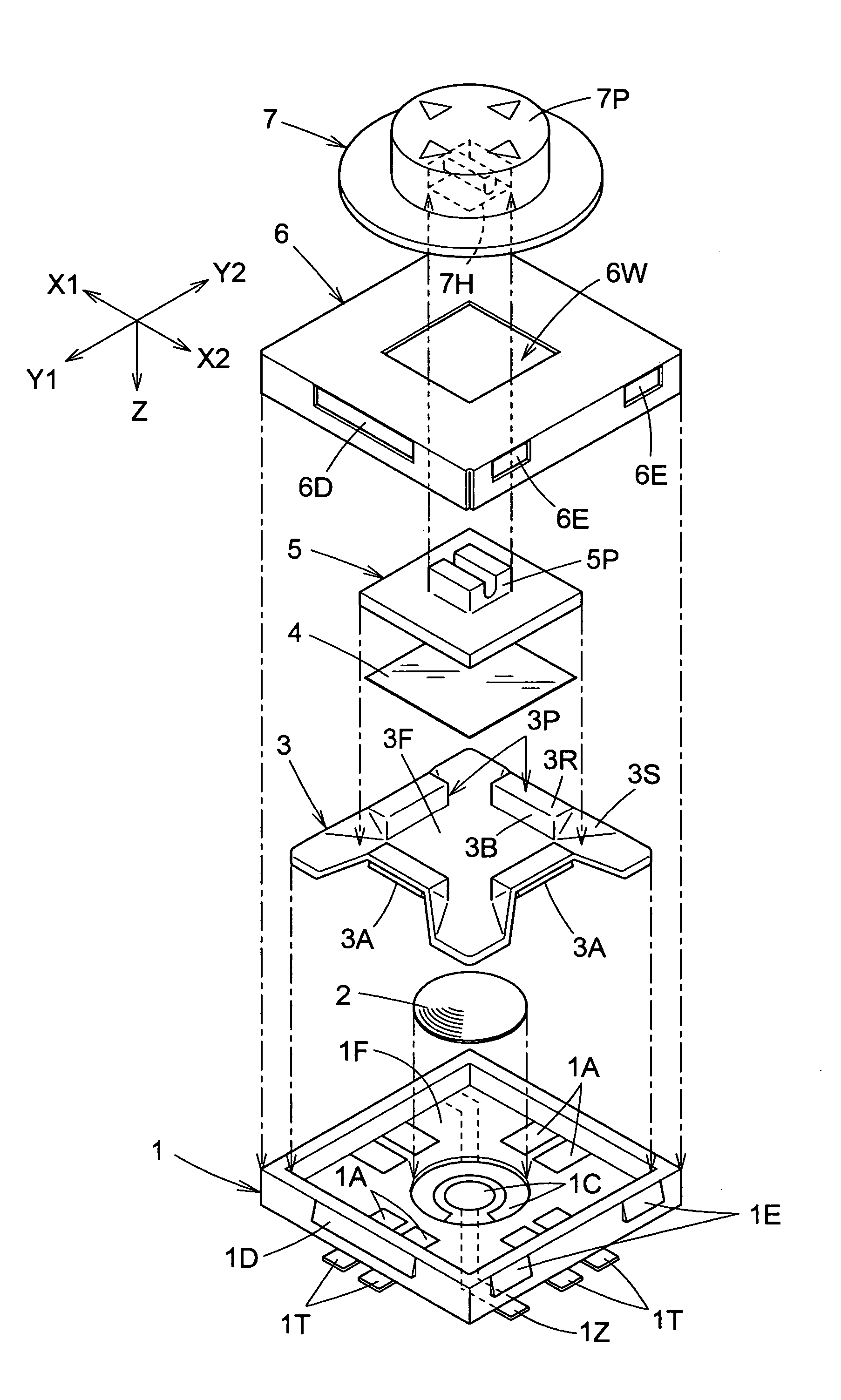
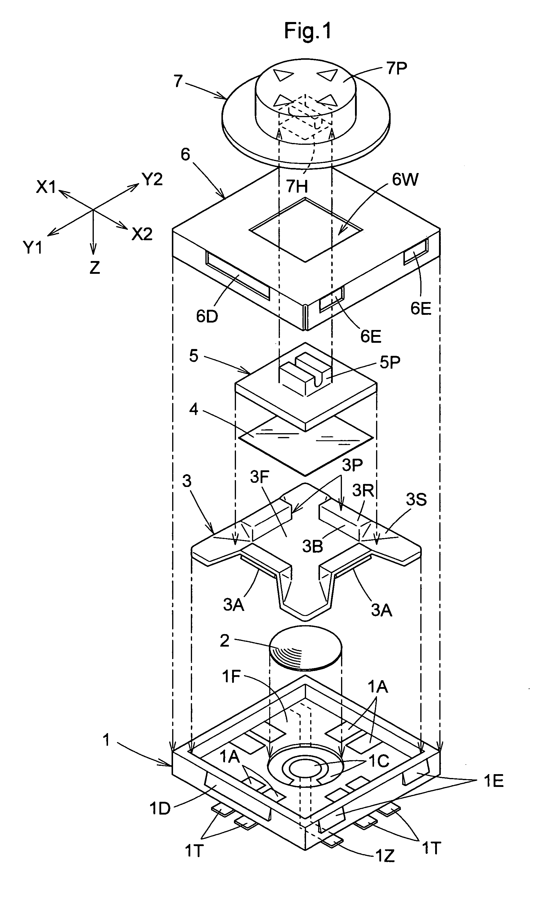
[0092]FIG. 7 is an exploded perspective view of a slide switch in a first modified embodiment of this invention. As shown, a slide switch includes a case 11, a metallic dome 12 acting as a second electric conductor, a biasing member 13, a sheet 14, a slider 15 acting as a slide member, a cover 16 and a keytop 17 successively stacked on upon another.

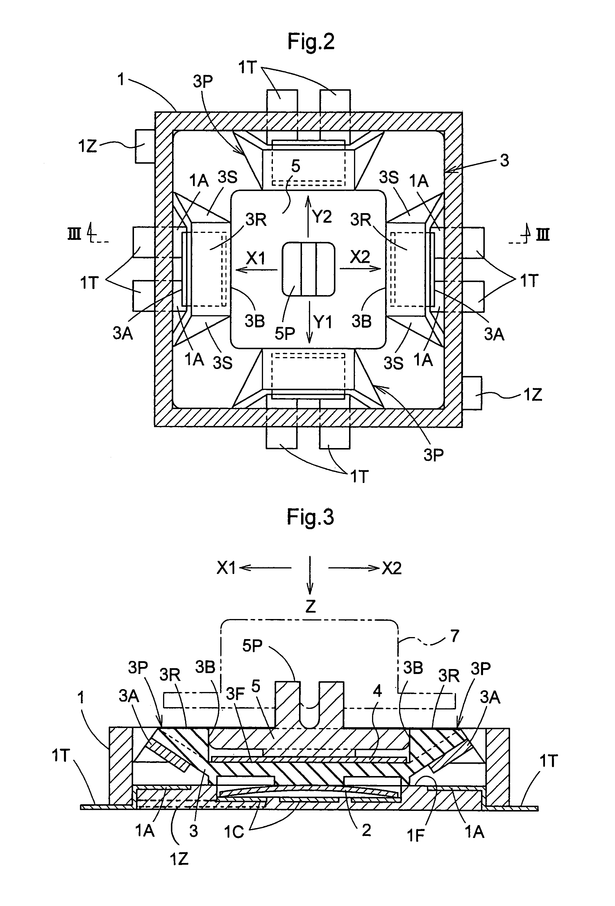
[0093]The biasing member 13 includes two projections 13P, and the slider 15 is biased to a neutral position pinched between the two projections 13P. The slider 15 is slidable in directions of arrow X1 and arrow X2 against the biasing force of the projections 13P. The cover 16 has a rectangular window 16W which does not obstruct movement in the directions of arrows X1 and X2 of engaging projections 15P of the slider 15, but restricts movement in directions perpendicular to the directions of, arrows X1, X2 and Z (e.g. directions of arrows Y1 and Y2 shown in FIG. 1).

[0094]The window 16W of the cover 16 may be reduced in size to restrict move...

second modified embodiment

[0097]This invention of course is not limited to slide switches performing two types of operations, i.e. the sliding operation and depression, but is applicable also to slide switches without the depression mode.

[0098]FIG. 8 is an exploded perspective view of a slide switch in a second modified embodiment of this invention. As shown, the slide switch includes a case 21, a biasing member 23, a sheet 24, a slider 25 acting as a slide member, a cover 26 and a keytop 27 successively stacked on upon another.

[0099]The case 21 includes at least one electrode pair 21A arranged on the bottom. The biasing member 23 includes projections 23P each having a back wall portion extending upward from a flat floor portion for biasing the slider 25 to a neutral position, and an electric conductor 23A disposed opposite the back wall portion. In the example shown in FIG. 8, electrode pairs 21A are arranged at four edges of the bottom of the square case 21, and the projections 23P are provided at four edg...

third modified embodiment

[0101]FIG. 9 is an exploded perspective view of a slide switch in a third modified embodiment of this invention. As shown, the slide switch includes a case 31, a biasing member 33, a sheet 34, a slider 35 acting as a slide member, a cover 36 and a keytop 37 successively stacked on upon another.

[0102]In this embodiment, the biasing member 33 includes two projections 33P, and the slider 35 is biased to a neutral position pinched between the two projections 33P. The slider 35 is slidable in directions of arrow X1 and arrow X2 against the biasing force of the projections 33P. The cover 36 has a rectangular window 36W which does not obstruct movement in the directions of arrows X1 and X2 of engaging projections 35P of the slider 35, but restricts movement in directions perpendicular to the directions of arrows X1, X2 and Z (e.g. directions of arrows Y1 and Y2 shown in FIG. 1).

[0103]The window 36W of the cover 36 may be reduced in size to restrict movement in one of the directions of arro...


PUM


Abstract

A slide switch having a reduced number of parts and formed thin. The slide switch includes a case having first electrode pairs and a second electrode pair arranged in a bottom thereof, a slide member slidably mounted in the case, and a biasing member for biasing the slide member. The biasing member has projections formed on one surface of a floor thereof, and each having a back wall portion, and a first electric conductor disposed opposite the back wall portion. When the slide member is operated in the direction of one of the projections against a biasing force, the projection is elastically deformed whereby the electrodes of the first electrode pair become conductive through the first electric conductor. When the slide member in a neutral position is pressed in the direction of the floor, the electrodes of the second electrode pair become conductive through the second electric conductor.

Description

BACKGROUND OF THE INVENTION[0001]1. Field of the Invention[0002]This invention relates to a slide switch having a slide member slidably mounted in a case, and a biasing member for biasing the slide member to a neutral position, in which an electrically conductive state is produced by operating the slide member against the biasing force of the biasing member.[0003]Further, the invention relates to a slide switch of the multi-contact type that produces an electrically conductive state also when the slide member is depressed.[0004]2. Description of the Related Art[0005]A slide switch as noted above is described in Japanese patent application laid open under “kokai” No. H11-111119 (Patent Document 1) (see paragraphs 21-26, paragraph 31, FIG. 2, FIGS. 4-6 and FIGS. 8-11, for example). This slide switch is a multi-contact input device having a first switch operable by a depressing operation of a control member, and a plurality of second switches operable through a rocking operation of the...

Claims


Application Information

Patent Timeline
Patent Type & Authority Patents(United States)
IPC IPC(8): H01H25/00
CPCH01H25/002H01H15/005H01H15/102H01H2227/036H01H2025/004E03C1/04E03C2001/0414
Inventor NIIYAMA, TAKASHI
Owner HOSIDEN CORP
Why Eureka
Try Eureka