Discharge lamp lighting apparatus

a technology of discharge lamp and lighting apparatus, which is applied in the direction of electric variable regulation, process and machine control, instruments, etc., can solve the problems of non-uniform brightness of discharge lamp along longitudinal direction, prone to long life of discharge fluorescent lamp,

Inactive Publication Date: 2007-10-16
TDK CORPARATION
View PDF8 Cites 4 Cited by
  • Summary
  • Abstract
  • Description
  • Claims
  • Application Information

AI Technical Summary

Problems solved by technology

Recently, a cold-cathode fluorescent lamp (designated as “CCFL” hereinafter) used as a backlight for a liquid crystal panel is prone to be long, since the liquid crystal panel is becoming larger in size.
When a high voltage is applied across the CCFL through one electrode thereof to light up the CCFL, the CCFL may have non-uniform brightness along the longitudinal direction thereof.
Therefore, current flows supplied from the inverter circuits may become unbalanced even if the same voltage is applied across the respective inverter circuits to light up the CCFL by the differential drive method.
However, when this method is employed, the duties of the inverters are generally different from each other.
Therefore, the inverter circuit which generates a larger duty pulse is required to have a larger derating, which raises a problem against downsizing of the discharge lamp lighting device.

Method used


Image

  • Discharge lamp lighting apparatus
  • Discharge lamp lighting apparatus
  • Discharge lamp lighting apparatus

Examples


Embodiment Construction

[0020]An embodiment according to the present invention will be described below with reference to the accompanying drawings.

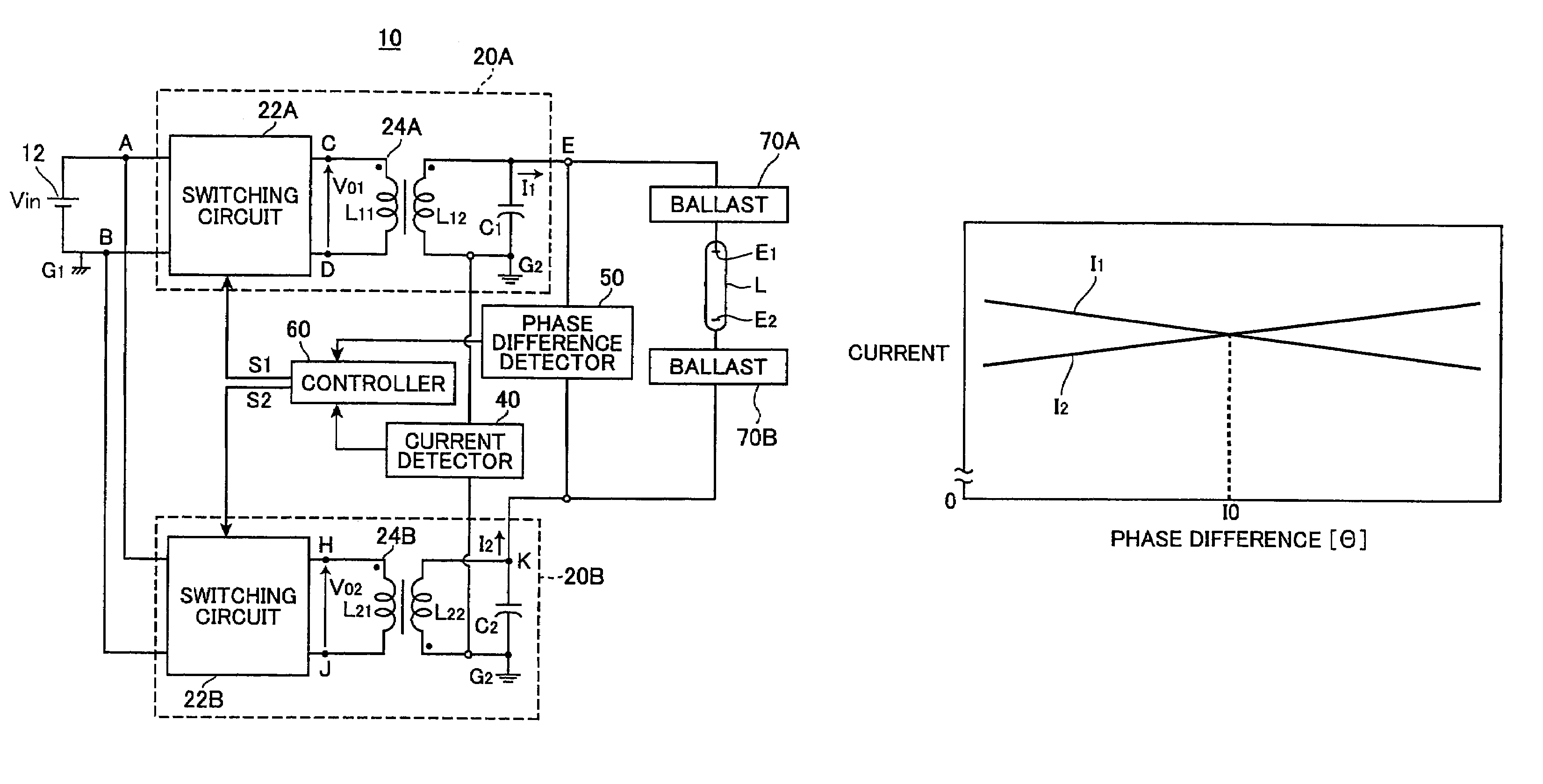
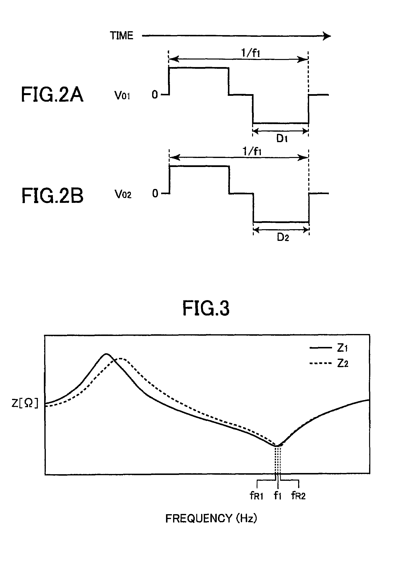
[0021]FIG. 1 shows a discharge lamp lighting device 10 according to an embodiment of the present invention. The discharge lamp lighting device 10 feeds electric power from a power supply to a discharge lamp L to light the discharge lamp L. The discharge lamp lighting device 10 includes a first drive circuit 20A, a second drive circuit 20B, an electric current detector 40, a phase difference detector 50, and a control circuit 60. The discharge lamp L controlled by the discharge lamp lighting device 10 is a CCFL that has electrodes E1, E2 at both ends thereof, respectively. In the following description, a voltage value, a current value, and an electric power value refer to an effective value, respectively, if not otherwise specified.

[0022]The first drive circuit 20A includes a first switching circuit 22A, a first transformer 24A, and a first resonant capacitor C1 ...


PUM


Abstract

The present invention provides a discharge lamp lighting apparatus for lighting a discharge lamp having two electrodes, having: a first drive circuit, a second drive circuit, and a control circuit. The first drive circuit is connectable to one of the two electrodes to supply a first alternating current to the discharge lamp. The first alternating current has a frequency and a first effective value. The second drive circuit is connectable to the other of the two electrodes to supply a second alternating current to the discharge lamp. The second alternating current has the frequency and a second effective value. The second alternating current has an opposite phase to the first alternating current. The control circuit generates first and second drive pulses to drive the first and second drive circuits, respectively. The first and second drive pulses have a phase difference therebetween. The control circuit adjusts the phase difference to match the first and second effective values.

Description

BACKGROUND OF THE INVENTION[0001]1. Technical Field[0002]The present invention relates to a discharge lamp lighting device that controls a discharge lamp having two electrodes. In particular, the present invention relates to a discharge lamp lighting device that controls a discharge lamp used as a backlight for various display panels such as big screen television sets.[0003]2. Related Art[0004]Recently, a cold-cathode fluorescent lamp (designated as “CCFL” hereinafter) used as a backlight for a liquid crystal panel is prone to be long, since the liquid crystal panel is becoming larger in size. When a high voltage is applied across the CCFL through one electrode thereof to light up the CCFL, the CCFL may have non-uniform brightness along the longitudinal direction thereof.[0005]Japanese Patent Application Publication 2004-241136 discloses a discharge lamp lighting device including a pair of inverter circuits, in which one of the inverter circuits as a master inverter circuit is conne...

Claims


Application Information

Patent Timeline
Patent Type & Authority Patents(United States)
IPC IPC(8): H05B37/02H01L41/08H02M7/497H05B41/24
CPCH05B41/3927H05B41/2828H05B41/36
Inventor NAKANISHI, HIROYUKI
Owner TDK CORPARATION
Why Eureka
Try Eureka