
Methods and apparatus for scatter correction

a scatter correction and apparatus technology, applied in applications, instruments, nuclear engineering, etc., can solve problems such as non-uniformity of ct number, reduced effective attenuation of imaged objects, and dark shading artifacts

Active Publication Date: 2007-10-16
GE YOKOGAWA MEDICAL SYST LTD +1
View PDF14 Cites 21 Cited by
  • Summary
  • Abstract
  • Description
  • Claims
  • Application Information

AI Technical Summary

Problems solved by technology

Scatter causes dark shading artifacts and CT Number non-uniformity in the objects being scanned, as well as a CT Number accuracy dependence on object size and aperture width.
Very low frequency scatter profile adds a positive bias to the detected radiation signal, thus reducing the effective attenuation of the imaged object, resulting in a negative bias in the measured Hounsfield Units (HU) in images.
Coupled with highly varying attenuation profiles of the object being imaged, scatter can cause differential artifacts, such as shading in uniform regions.

Method used


Image

  • Methods and apparatus for scatter correction
  • Methods and apparatus for scatter correction
  • Methods and apparatus for scatter correction

Examples


Embodiment Construction

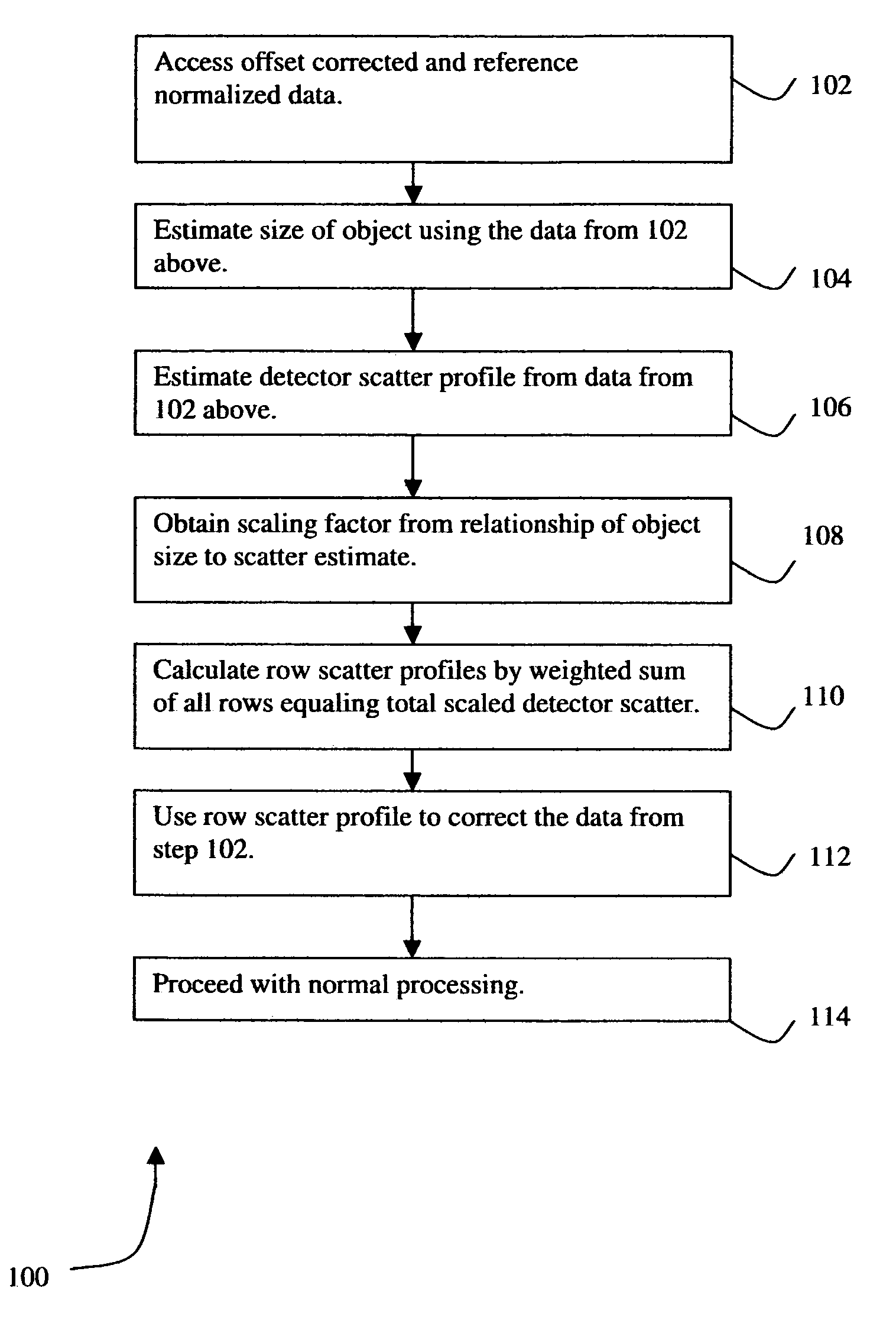
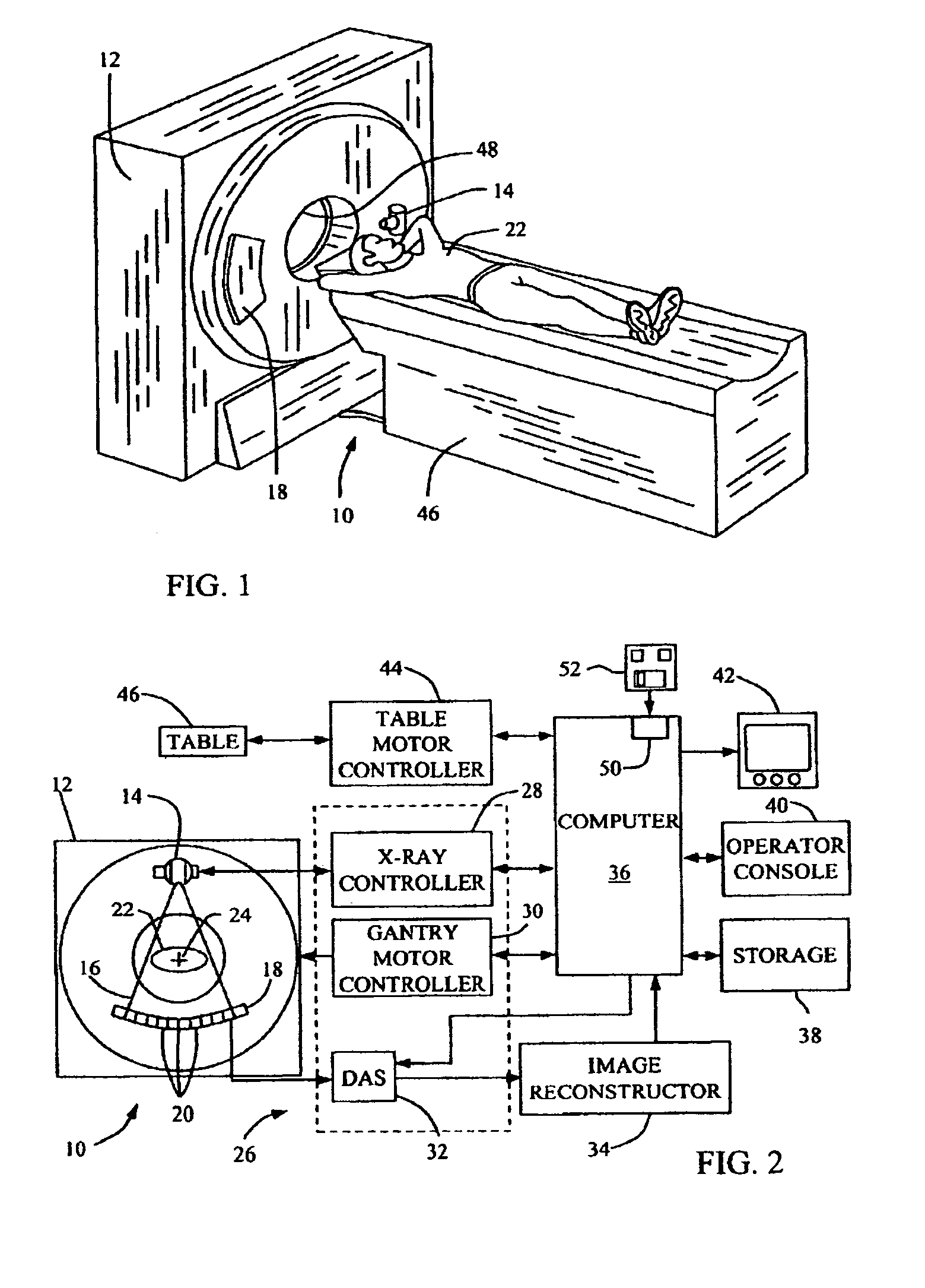
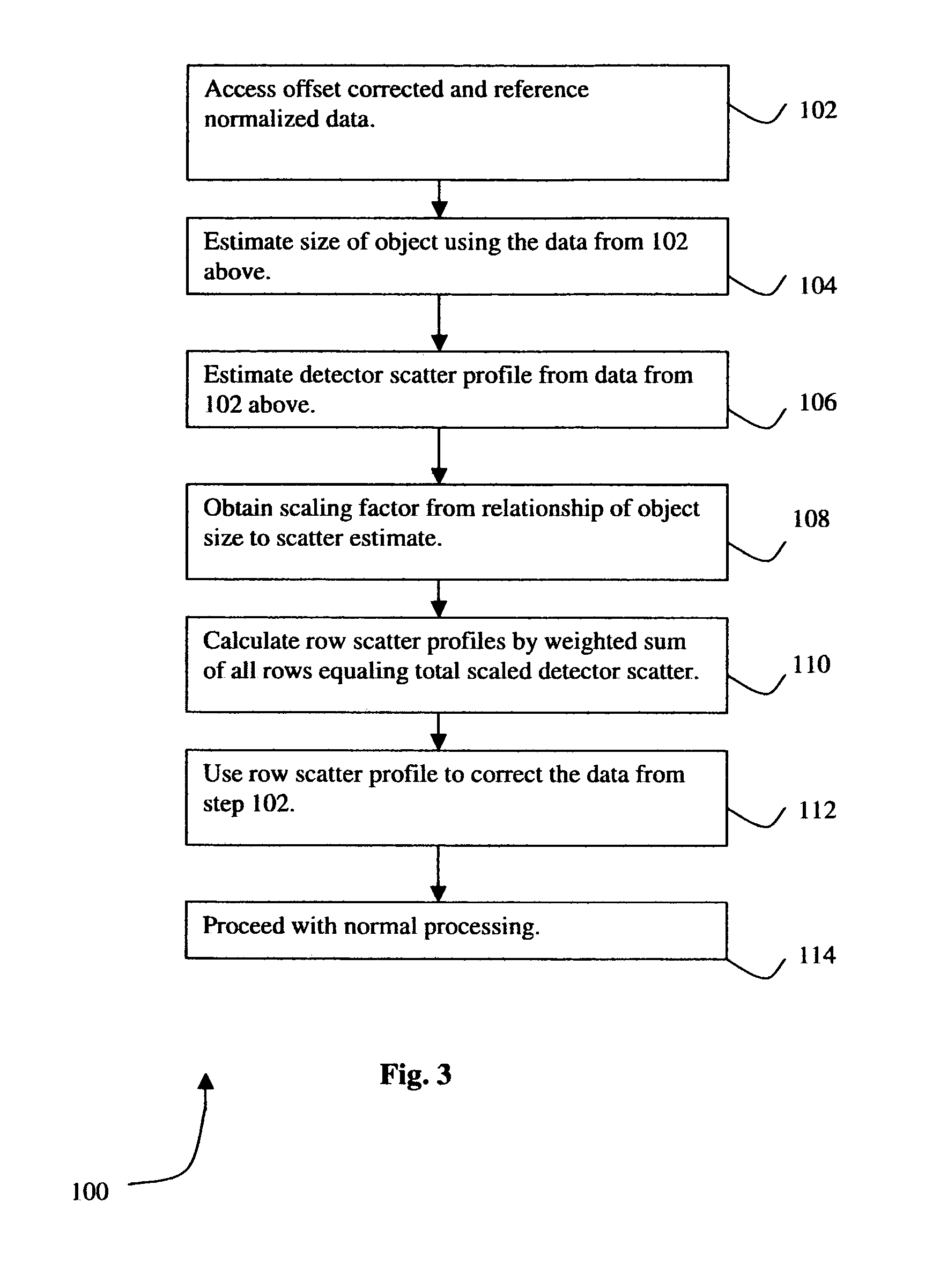
[0018]There are herein provided scatter correction methods and apparatus useful for imaging systems such as, for example, but not limited to a Computed Tomography (CT) System. The apparatus and methods are illustrated with reference to the figures wherein similar numbers indicate the same elements in all figures. Such figures are intended to be illustrative rather than limiting and are included herewith to facilitate explanation of an exemplary embodiment of the apparatus and methods of the invention.

[0019]In some known CT imaging system configurations, a radiation source projects a fan-shaped beam which is collimated to lie within an X-Y plane of a Cartesian coordinate system and generally referred to as an “imaging plane”. The radiation beam passes through an object being imaged, such as a patient. The beam, after being attenuated by the object, impinges upon an array of radiation detectors. The intensity of the attenuated radiation beam received at the detector array is dependent...


PUM


Abstract

A method for reconstructing an image of an object includes scanning the object with a computed tomography (CT) system to obtain data, estimating a size of the object using the obtained data, using the estimated size of the object to perform scatter correction on the obtained data, and reconstructing an image using the scatter corrected data.

Description

BACKGROUND OF THE INVENTION[0001]This invention relates generally to methods and apparatus for computed tomography (CT), and more particularly to methods and apparatus that provide for 3D scatter correction.[0002]Cone Beam Multi-Slice Computed Tomography (CT) Systems have wider Z-Axis coverage than traditional MultiDetector CT systems (MDCT). The traditional MDCT systems were limited to beam widths of 20 mm or lower. With the advent of Cone Beam Multi-Slice systems, the new beam width is more than double the beam width of traditional MDCT systems. These new systems are typically more sensitive to the effect of scattered radiation (scatter). Scatter can be described as spurious radiation due to X-rays bouncing off the internal components of the CT system or the object being scanned. The effective correction for scatter is more important when the CT detector is not effectively collimated to reject scattered radiation.[0003]Scatter causes dark shading artifacts and CT Number non-unifor...

Claims


Application Information

Patent Timeline
Patent Type & Authority Patents(United States)
IPC IPC(8): H05G1/60
CPCG06T11/005Y10S378/901A61B6/027
Inventor SAINATH, PAAVANAWU, XIAOYENUKUI, MASATAKELUNDGREN, RONALD JOSEPHMYERS, THOMAS JOHN
Owner GE YOKOGAWA MEDICAL SYST LTD
Learn More