Optical connector with protective cover and leaf spring

a technology of optical connectors and leaf springs, applied in the field of optical plugin connections, can solve the problems of all the greater the size of the connectors, and achieve the effect of reducing the size of the connector

Inactive Publication Date: 2007-10-16
HUBERSUHNER AG
View PDF10 Cites 16 Cited by
  • Summary
  • Abstract
  • Description
  • Claims
  • Application Information

AI Technical Summary

Benefits of technology

[0009]The object of the invention is to provide an optical connector on which the pivotable protective cover is prestressed in the closing direction by spring means and which can be assembled without difficulty, and in particular also automatically, even with further reduced dimensions.
[0011]A first preferred configuration of the invention is distinguished by the fact that the leaf spring is restrained with its one end on the housing in a predetermined position of rest, that the leaf spring is arranged with its other, free end in relation to the cover in such a way that, during the pivoting of the cover from the first position into the second position, the leaf spring is bent with the free end out of its position of rest, that the optical fiber in the connector runs parallel to a connector axis, that the cover can be pivoted about a pivot axis lying transversely in relation to the connector axis, and that the leaf spring in its position of rest on the housing rests on a supporting surface, the surface normal of which is oriented perpendicularly in relation to the pivot axis and runs parallel to the connector axis. The arrangement of the leaf spring parallel to the connector axis allows a comparatively long leaf spring, which has a favorable spring characteristic for the actuation of the cover, to be accommodated on the connector. The resting on a supporting surface leads to stable restraint of the leaf spring and to high functional reliability.
[0012]According to a preferred development of the configuration, for restraining one end of the leaf spring on the housing, the leaf spring rests with the end on the supporting surface on the housing and is held down on the supporting surface by hold-down devices arranged above the supporting surface on the housing and extending parallel to the supporting surface, it being possible for the leaf spring to be pushed in between the supporting surface and the hold-down devices. This configuration ensures that the leaf springs can be pushed very easily in between the supporting surface and the hold-down devices during assembly.
[0014]In order that the leaf spring can be assembled more easily, it is of advantage if the slit-like clearance in the leaf spring has a funnel-shaped widening toward the open side.
[0016]In this connection, a bistable pivoting mechanism for the cover can be realized by the actuating elements or studs being arranged on the cover in such a way that a maximum deflection of the leaf spring is achieved when the cover is in a predetermined pivoting position, which lies between the first position and the second position, and by the cover being pressed into the second position by the leaf spring when it has exceeded the predetermined pivoting position while coming from the first position.
[0017]Another preferred configuration of the invention is characterized in that the leaf spring is fixedly arranged with its one end in the cover itself and, during the pivoting of the cover, slides with a free end along on a sliding surface formed on the housing in such a way that the cover is prestressed in the closing direction. This type of arrangement is particularly advantageous if, according to a development, the leaf spring is fastened to the cover in such a way that, when the cover is closed, it intercepts radiation emerging from the optical fiber and the part of the leaf spring that lies in the path of rays of the optical fiber when the cover is closed is set obliquely in relation to the optical axis of the optical fiber in such a way that radiation impinging on the leaf spring from the optical fiber is not reflected back into the optical fiber.

Problems solved by technology

Problems when spiral springs are used for prestressing the protective covers in the closing direction arise in particular because the spiral springs are difficult to handle during assembly and in particular cause problems in automated assembly.
These problems become all the greater the smaller the connectors become.

Method used


Image

  • Optical connector with protective cover and leaf spring
  • Optical connector with protective cover and leaf spring
  • Optical connector with protective cover and leaf spring

Examples


Embodiment Construction

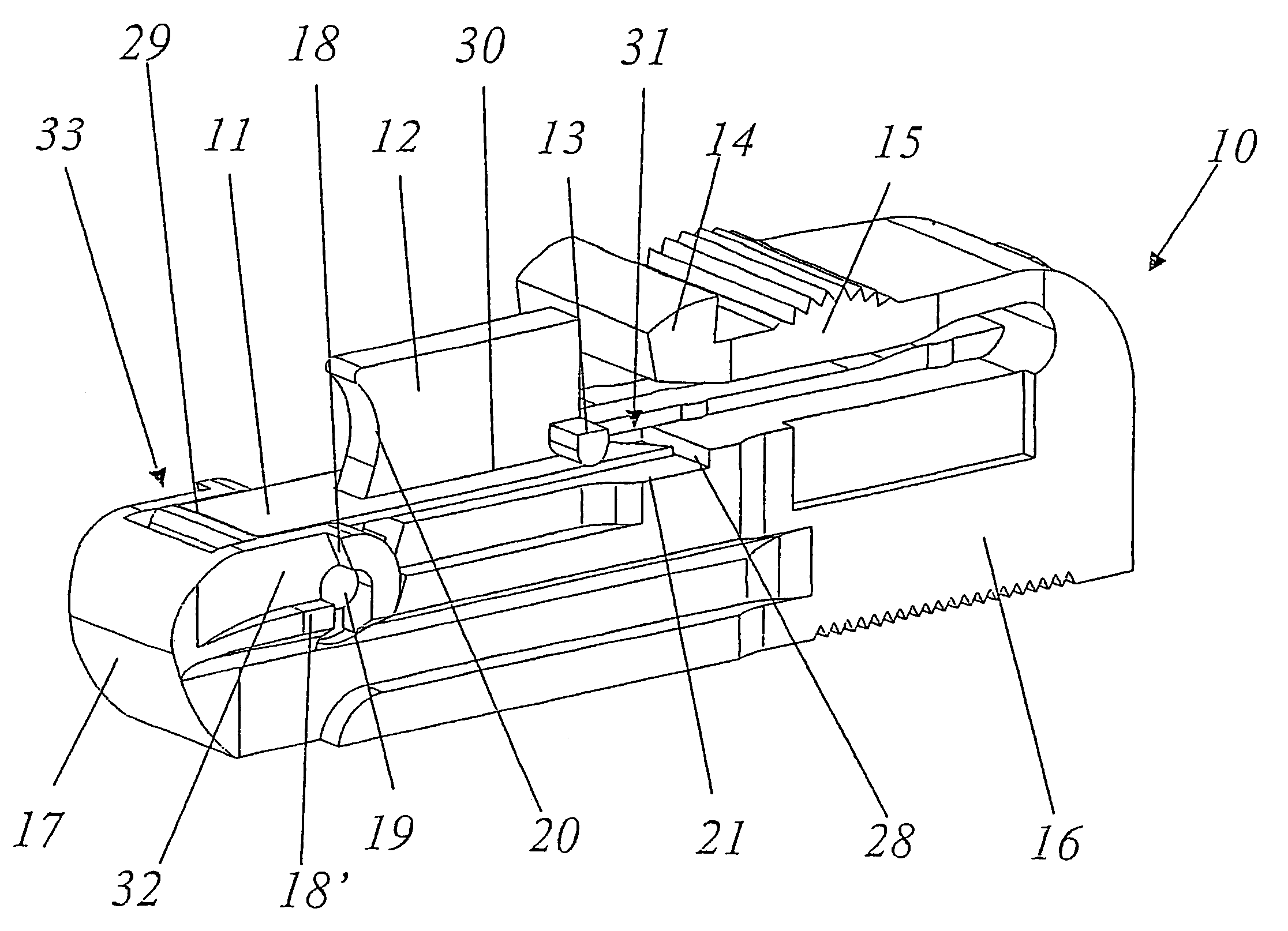
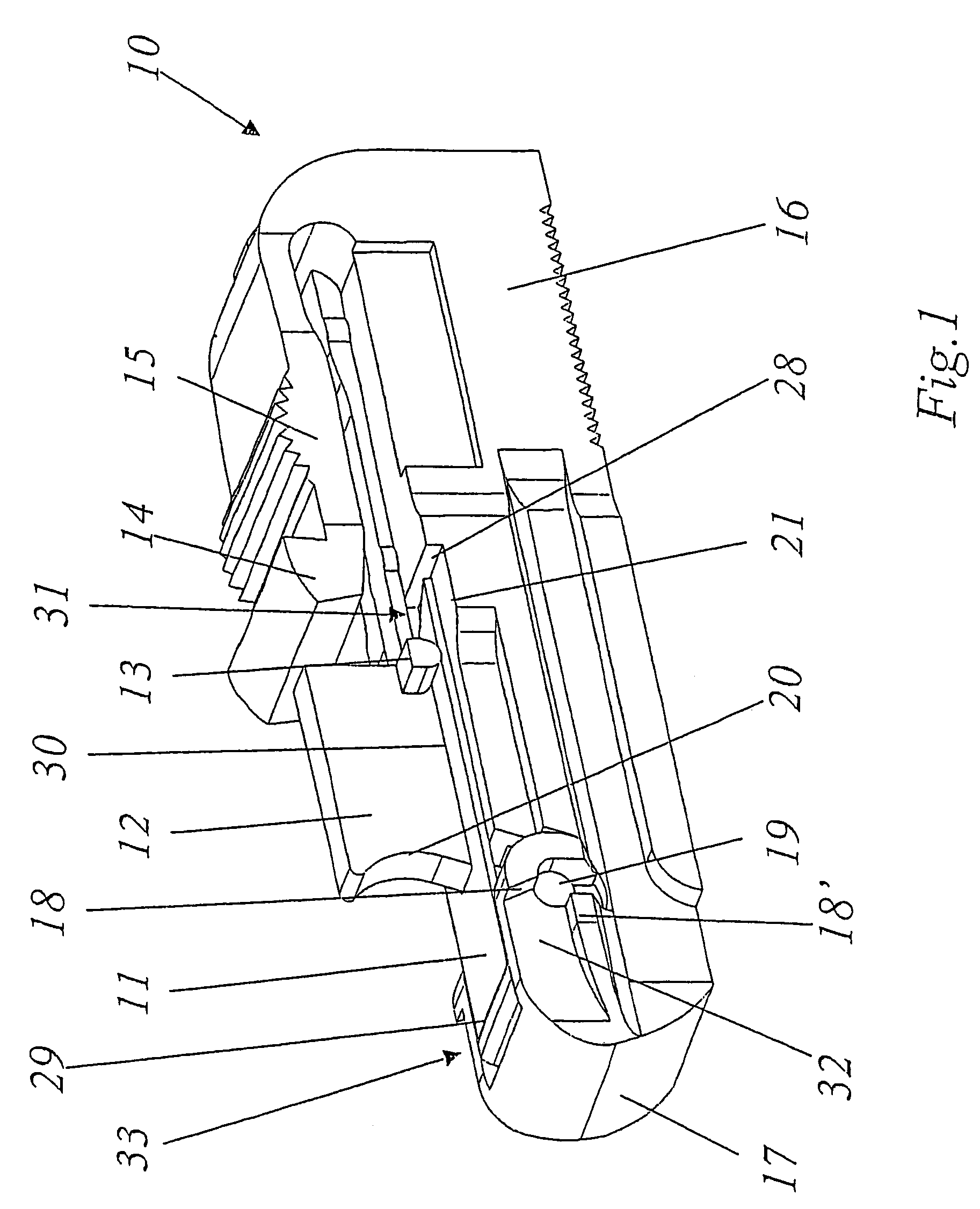
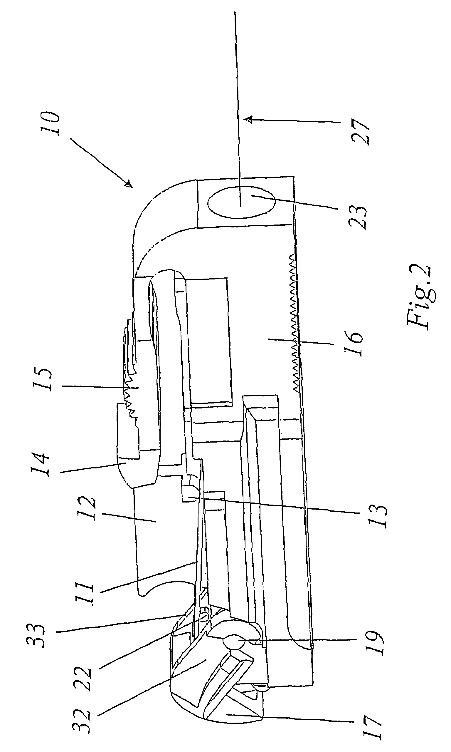
[0023]In FIGS. 1 to 3, a preferred exemplary embodiment of a connector 10 according to the invention is reproduced in a perspective representation, the cover 17 provided on the connector 10 assuming different positions in the figures. The connector 10 has a housing 16 made of a suitable plastic, through which there runs in the longitudinal direction, along a connector axis 27 (FIG. 2), a through-bore, which emerges to the outside at the rear end of the connector 10 in a first opening 23 (FIG. 2) and at the front end in a second opening 25 (FIG. 3). The cable with the optical fiber is introduced into the connector 10 through a kink preventer by being inserted into the rear, first opening 23. From the front, second opening 25 there protrudes from the interior of the connector 10 a ferrule 24, in the central bore of which the end of the optical fiber 26 is accommodated (FIG. 3). For further details of the internal structure, reference should be made to the configuration given by way of...


PUM


Abstract

The invention relates to an optical connector for connecting optical fibers. Said connector comprises a housing which is provided with a first opening for an optical cable comprising an optical fiber to be connected, and a second opening, through which the end of the optical fiber outwardly protrudes from the housing. The second opening can be closed by a lid which can be pivoted between a first position in which it closes the second opening, and a second position in which it frees the second opening. Spring elements are provided for prestressing the lid in the closing direction. The aim of the invention is to simplify the structure and especially the assembly of one such connector. To this end, the spring elements comprise a laminated spring.

Description

BACKGROUND OF THE INVENTIONField of the Invention[0001]The present invention relates to the field of optical plug-in connections.Description of Related Art[0002]In fiber-optic communications technology, use has long been made of optical connector systems in which two optical fibers are coupled to each other by two connectors, in each of which one of the fibers ends in a ferrule, being inserted from opposite sides into a coupling or an adapter in such a way that the ferrules slide from both sides into a guiding sleeve arranged in the coupling and butt with the end faces against each other. Connector systems of this type are known and marketed under the designation SC, LC, E2000,LSH or LX.5.[0003]In some of the known connector systems, the connectors are equipped with pivotable protective covers, which in the non-inserted state of the connector cover the opening from which the ferrule protrudes with the end of the fiber and so on the one hand protect the sensitive coupling-in surface ...

Claims


Application Information

Patent Timeline
Patent Type & Authority Patents(United States)
IPC IPC(8): G02B6/00G02B6/36G02B6/38
CPCG02B6/3849G02B6/3893
Inventor ZAINA, PATRICKFRISCHKNECHT, URS
Owner HUBERSUHNER AG
Why Eureka
Try Eureka