Image heating apparatus using flexible sleeve

a flexible sleeve and heating apparatus technology, applied in the direction of electrographic process apparatus, instruments, optics, etc., can solve the problems of difficult to regulate the lateral shift force, the end of the film may be damaged, and the fix device according to the heating roller system requires a lot of time, so as to prevent the deterioration of the durability of the flexible sleeve

Active Publication Date: 2007-10-16
CANON KK
View PDF20 Cites 33 Cited by
  • Summary
  • Abstract
  • Description
  • Claims
  • Application Information

AI Technical Summary

Benefits of technology

[0014]The object of the present invention is to solve the above problem and its object is to provide an image heating apparatus capable of preventing deterioration of the durability of a flexible sleeve.

Problems solved by technology

However, because the fixing device according to the heating roller system requires a lot of time in order to raise the temperature of roller surface up to a fixing temperature because the rollers respectively have a large heat capacity.
In the case of these film-heating-system fixing devicees, lateral shift to the generatrix direction (thrust direction) may occur in a film and it is difficult to regulate the lateral shift force.
Therefore, the end of the film may be damaged.
However, in the case of a fixing belt using a metallic film, the fixing film itself has a high stiffness and lacks in flexibility.
Therefore, when the shift of parallelism between the above pressure rollers and film or the difference between right and left applied pressures arises and a strong lateral shift force is generated and a film locally receives a stress on the lateral shift regulation surface, cracks may arise from an end.

Method used


Image

  • Image heating apparatus using flexible sleeve
  • Image heating apparatus using flexible sleeve
  • Image heating apparatus using flexible sleeve

Examples


embodiment 1

(1) Embodiment of Image Forming Apparatus

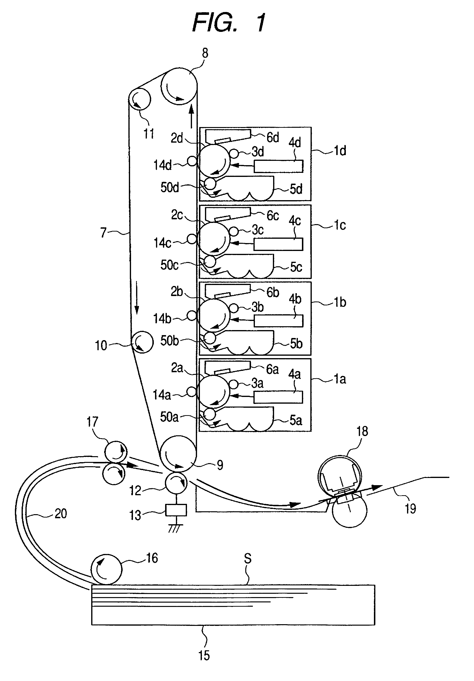
[0035]An embodiment of an image forming apparatus using an image heating apparatus of the present invention as a fixing device is described below by referring to FIG. 1.

[0036]The image forming apparatus of this embodiment is a full-color image forming apparatus using an electrophotographic system. The apparatus has four process stations 1a to 1d arranged on an substantial straight line in a substantial vertical direction to the setting face of the apparatus to form four different color images (magenta, cyan, yellow and black) and a conveying route 20 for conveying sheets S serving as recording materials (recording media).

[0037]The process stations 1a to 1d have photosensitive drums 2a to 2d for bearing a latent image. Moreover, the process stations 1a to 1d have electrification rollers 3a to 3d for uniformly electrifying the photosensitive drums 2a to 2d and exposure devices 4a to 4d for applying a laser beam on the photosensitive drums 2a to...


PUM


Abstract

An image heating apparatus includes a flexible sleeve, a sliding member for sliding on the inner periphery of the sleeve, and a back-up member for forming a nip portion together with the sliding member through the sleeve. A recording material for bearing an image is heated while being held and conveyed by the nip portion, and a regulation member is set by facing the edge surface of the sleeve in the generatrix direction to regulate the movement of the sleeve in the generatrix direction, the regulation member having a regulation surface with which the edge surface of the sleeve contacts when the sleeve moves in the generatrix direction. The regulation surface of the regulation member has a curved-surface area in which a line when the regulation surface is cut at a virtual plane almost parallel with the nip portion is a curved line expanded toward the edge surface of the sleeve. Thereby, an image heating apparatus is provided which is able to restrain deterioration of the durability of the flexible sleeve.

Description

BACKGROUND OF THE INVENTION[0001]1. Field of the Invention[0002]The present invention relates to an image heating apparatus for heating an image born by a recording material by passing the recording material through a fixing nip portion N between a heat member and a pressuring member to cause the material to be held and conveyed. Particularly, the present invention relates to an image heating apparatus to be preferably mounted on an image forming apparatus such as a copying machine or printer as an image heating-fixing device.[0003]More minutely, the present invention includes a flexible sleeve-shaped rotor, a sliding member set to the inside of the rotor to slide on the inner periphery of the rotor, a pressuring member for forming a nip portion together with the sliding member by holding the rotor and a regulation member set by facing the end of the rotor to regulate movement of the rotor in a generatrix direction, which heats a recording material bearing an image by the nip portio...

Claims


Application Information

Patent Timeline
Patent Type & Authority Patents(United States)
IPC IPC(8): G03G15/20
CPCG03G15/2053G03G2215/2035G03G2215/2016G03G2215/00151
Inventor UCHIDA, MICHIOSHIMIZU, YUUSUKEINO, KAZUSHI
Owner CANON KK
Why Eureka
Try Eureka