In-line measuring device

a technology of in-line measuring and measuring device, which is applied in the direction of direct mass flowmeter, liquid/fluent solid measurement, volume measurement, etc., can solve the problems of considerable effort for the startup of measurement pickup, the firmware stored and executed in the digital measurement circuit is correspondingly complex, and the area of measurement value production is required to make significant changes

Active Publication Date: 2007-10-23
ENDRESS HAUSER FLOWTEC AG
View PDF52 Cites 88 Cited by
  • Summary
  • Abstract
  • Description
  • Claims
  • Application Information

AI Technical Summary

Benefits of technology

[0039]An advantage of the invention is that the correction values to be determined are well reproducible over a large range of application and, also, the forming rules for determining the correction values during measurement operation can be formulated relatively simply.
[0040]Moreover, these forming rules can be calculated initially with a relatively small effort. A further advantage of the invention is, additionally, to be seen in the fact that, in the case of the inline measuring device of the invention, as compared to a conventional type, especially such as described in WO-A 03 / 095950, WO-A 03 / 095949 or U.S. Pat. No. 4,524,610, only in the case of the usually digital, measured value production do slight changes have to be made, these being essentially limited to the firmware, while, both in the case of the measurement pickup and in the production and preprocessing of the oscillation measurement signals, no, or only slight, changes are required. Thus, for example, even in the case of two, or more, media, the oscillation measurement signals can be sampled, as before, with a usual sampling ratio of far under 100:1, especially of about 10:1.

Problems solved by technology

However, a considerable disadvantage of such classifiers includes, among others, that, in comparison to conventional Coriolis mass flow measuring devices, considerable changes are required in the area of the measured value production, above all with regards to the analog-to-digital transducer being used and the microprocessors.
Beyond this, also the firmware stored and executed in the digital measurement circuit is correspondingly complex.
A further disadvantage of such classifiers is that they must be trained and correspondingly validated for the conditions of measurement actually existing during operation of the measurement pickup, be it regarding the particulars of the installation, the medium to be measured and its usually variable properties, or other factors influencing the accuracy of measurement.
Because of the high complexity of the interplay of all these factors, the training and its validation can occur ultimately only on site and individually for each measurement pickup, this in turn meaning a considerable effort for the startup of the measurement pickup.
Finally, it has been found, that such classifier algorithms, on the one hand because of the high complexity, on the other because of the fact that usually a corresponding physical-mathematical model with technically relevant or comprehensible parameters is not explicitly present, exhibit a very low transparency and are, consequently, often difficult to explain.
Accompanying this situation, it is clear that considerable reservations can occur on the part of the customer, with such acceptance problems especially arising when the classifier, additionally, is self-adapting, for example a neural network.
Here, however, one is dealing with a very special solution which cannot always be implemented, without more, in the technology of industrial process measurement.
On the one hand, in this case, it can happen, namely, that the pipeline, into which the measurement pickup is to be inserted, might have to be adapted to the measurement pickup, rather than the reverse, which can mean an increased expense for implementing the measurement location.
On the other hand, as already mentioned, the measuring tubes might have a curved shape, in which case the problem cannot always be solved satisfactorily by an adapting of the installation orientation anyway.
It has, moreover, been found in this case that the aforementioned corruptions of the measurement signal are not necessarily prevented with certainty by the use of a vertically installed, straight measuring tube anyway.

Method used


Image

  • In-line measuring device
  • In-line measuring device
  • In-line measuring device

Examples


Embodiment Construction

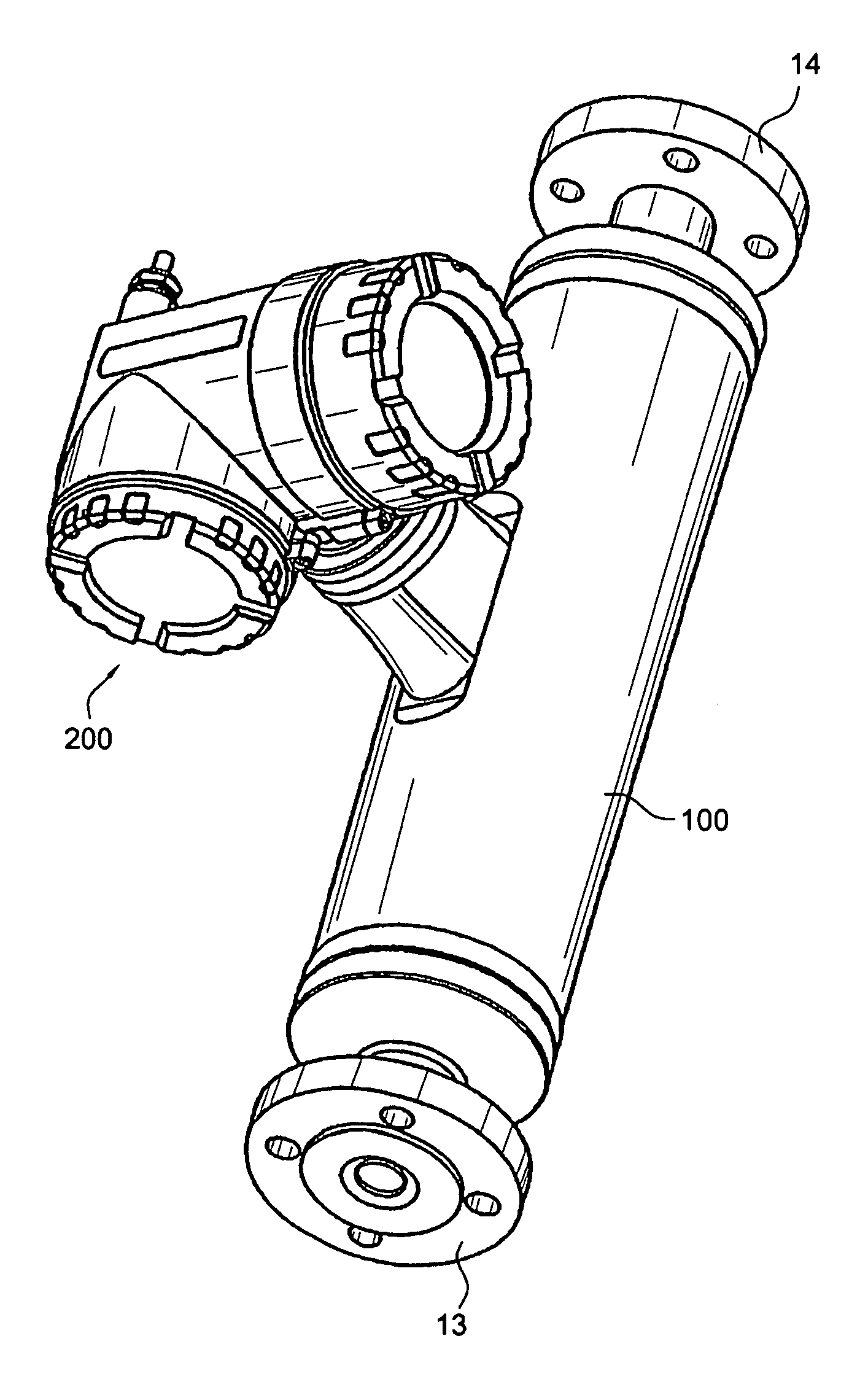
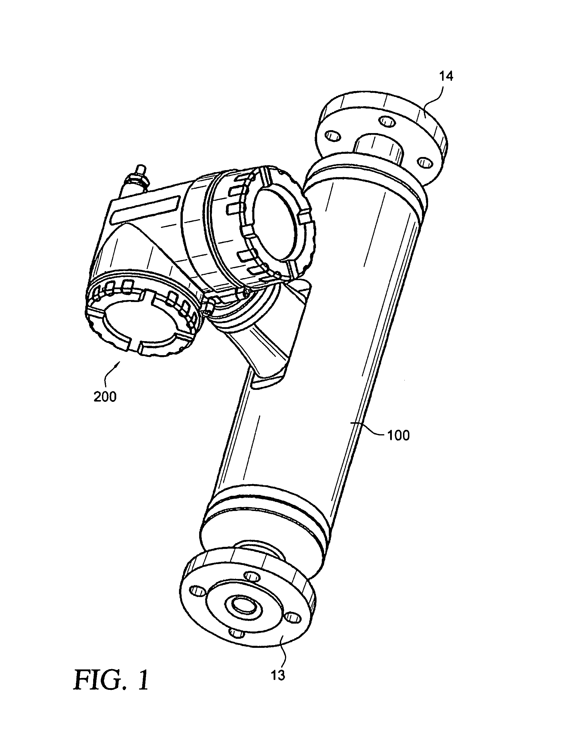
[0050]FIG. 1 shows, perspectively, an inline measuring device 1 suited for registering a physical, measured quantity, e.g. a mass flow rate m, a density ρ and / or a viscosity η, of a medium flowing in a pipeline (not shown) and for imaging this measured quantity in an instantaneously representing, measured value XX. The medium in this instance can be practically any flowable substance, for example a liquid, a gas, a vapor, or the like.

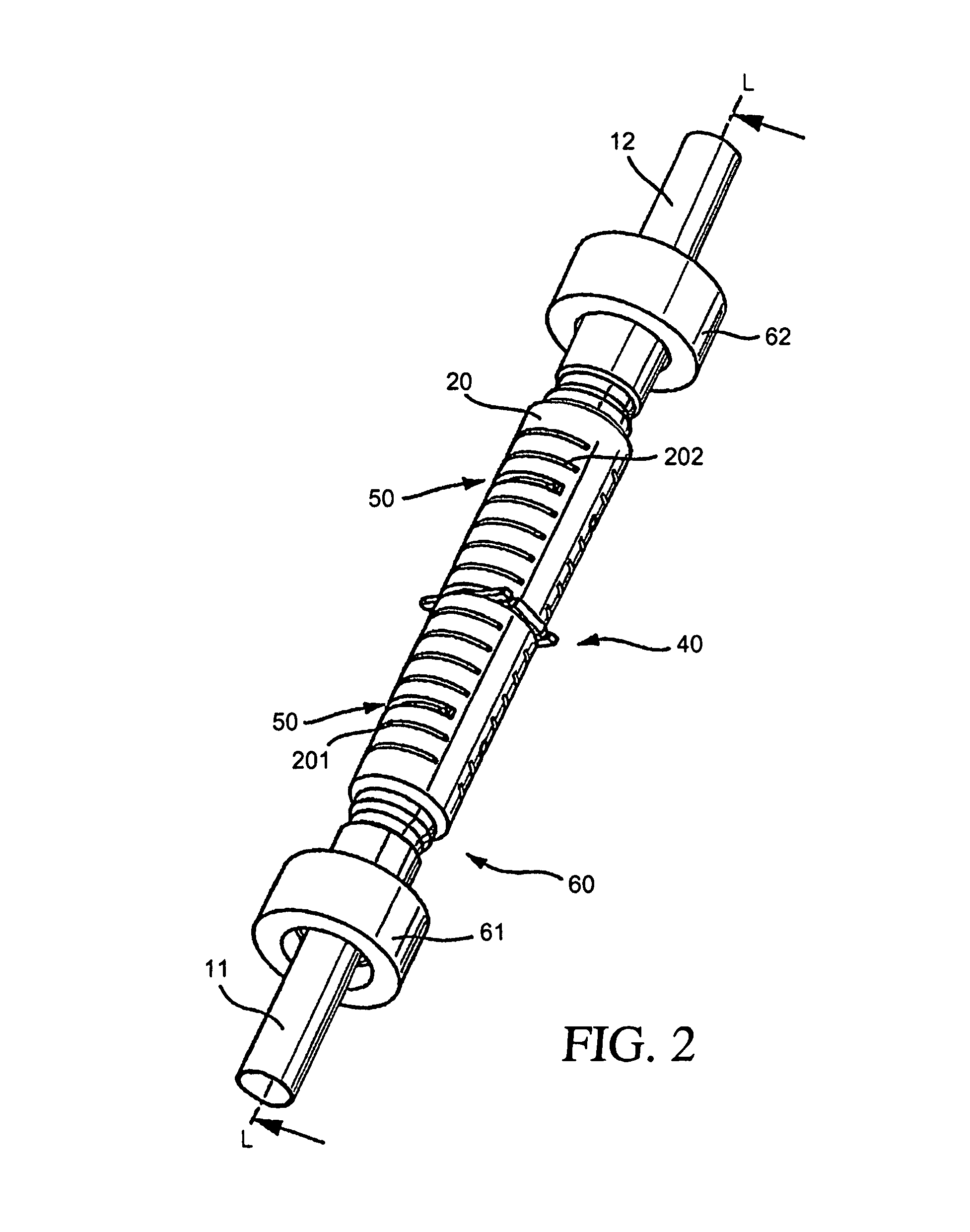
[0051]The inline measuring device 1, for example provided in the form of a Coriolis mass flow, density and / or viscosity meter, includes therefor a vibratory measurement pickup 10 flowed-through by the medium to be measured, an example of an embodiment and developments being shown in FIGS. 2 to 6, together with a measuring device electronics 50, as illustrated schematically in FIGS. 2 and 7. Preferably, the measuring device electronics 50 is, additionally, so designed that it can, during operation of the inline measuring device 1, exchange measurement an...


PUM


Abstract

An inline measuring device includes a vibration-type measurement pickup having at least one measuring tube, which has a medium to be measured flowing through it during operation. The measuring tube is made by means of an exciter arrangement to execute, at least at times and / or at least in part, lateral oscillations and, at least at times and / or at least in part, torsional oscillations about an imaginary measuring tube longitudinal axis. The torsional oscillations alternate with the lateral oscillations or are, at times, superimposed thereon. Also included is a sensor arrangement for producing oscillation measurement signals correspondingly representing oscillations of the measuring tube. Measuring device electronics controlling the exciter arrangement generates, by means of at least one of the oscillation measurement signals and / or by means of the exciter current, at least at times, at least one measured value, which represents the at least one physical quantity to be measured. Additionally, the measuring device electronics also determines a first intermediate value, which corresponds to the lateral current component of the exciter current serving to maintain the lateral oscillations of the measuring tube and / or to a damping of the lateral oscillations of the measuring tube, as well as a second intermediate value, which corresponds to a torsional current component of the exciter current serving to maintain the torsional oscillations of the measuring tube and / or to a damping of the torsional oscillations of the measuring tube. With the goal of producing the measured value at high accuracy, such value is determined also taking into consideration these two intermediate values. The measured value obtained in this way is distinguished especially by high accuracy also in the case of media of two, or more, phases.

Description

FIELD OF THE INVENTION[0001]The invention relates to an inline measuring device having a vibratory-type measurement pickup, especially a Coriolis mass-flow / density measuring device for a medium, especially a two, or more, phase medium flowing in a pipeline, as well as a method for producing by means of such a measurement pickup a measured value representing a physical, measured quantity of the medium, for example a mass flow rate, a density and / or a viscosity.BACKGROUND OF THE INVENTION[0002]In the technology of process measurements and automation, the measurement of physical parameters of a medium flowing in a pipeline, parameters such as e.g. the mass flow rate, density and / or viscosity, such inline measuring devices, especially Coriolis mass flow measuring devices, are used, which bring about reaction forces in the medium, such as e.g. Coriolis forces corresponding to the mass flow rate, inertial forces corresponding to the density, or frictional forces corresponding to the visco...

Claims


Application Information

Patent Timeline
Patent Type & Authority Patents(United States)
IPC IPC(8): G01F1/84
CPCG01F1/8409G01F1/8413G01F1/8418G01F1/8427G01F1/8436G01F1/849G01F15/024G01F1/8431G01N2009/006G01N11/16
Inventor RIEDER, ALFREDDRAHM, WOLFGANGFUCHS, MICHAELSPRICH, HANS-JORGITIN, IBHOWYSS, SAMUEL
Owner ENDRESS HAUSER FLOWTEC AG
Why Eureka
Try Eureka