
Portable raising and lowering device and equipment therefor

a technology of lifting and lowering device and equipment, which is applied in the direction of medical transportation, cranes, and portable lifting, etc., can solve the problems of noisy mechanisms, inconvenience for patients and operators alike, and devices provided with electric motors, and achieve the effect of improving design or operation

Inactive Publication Date: 2007-10-23
BRITISH COLUMBIA INSTITUTE OF TECHNOLOGY
View PDF22 Cites 27 Cited by
  • Summary
  • Abstract
  • Description
  • Claims
  • Application Information

AI Technical Summary

Benefits of technology

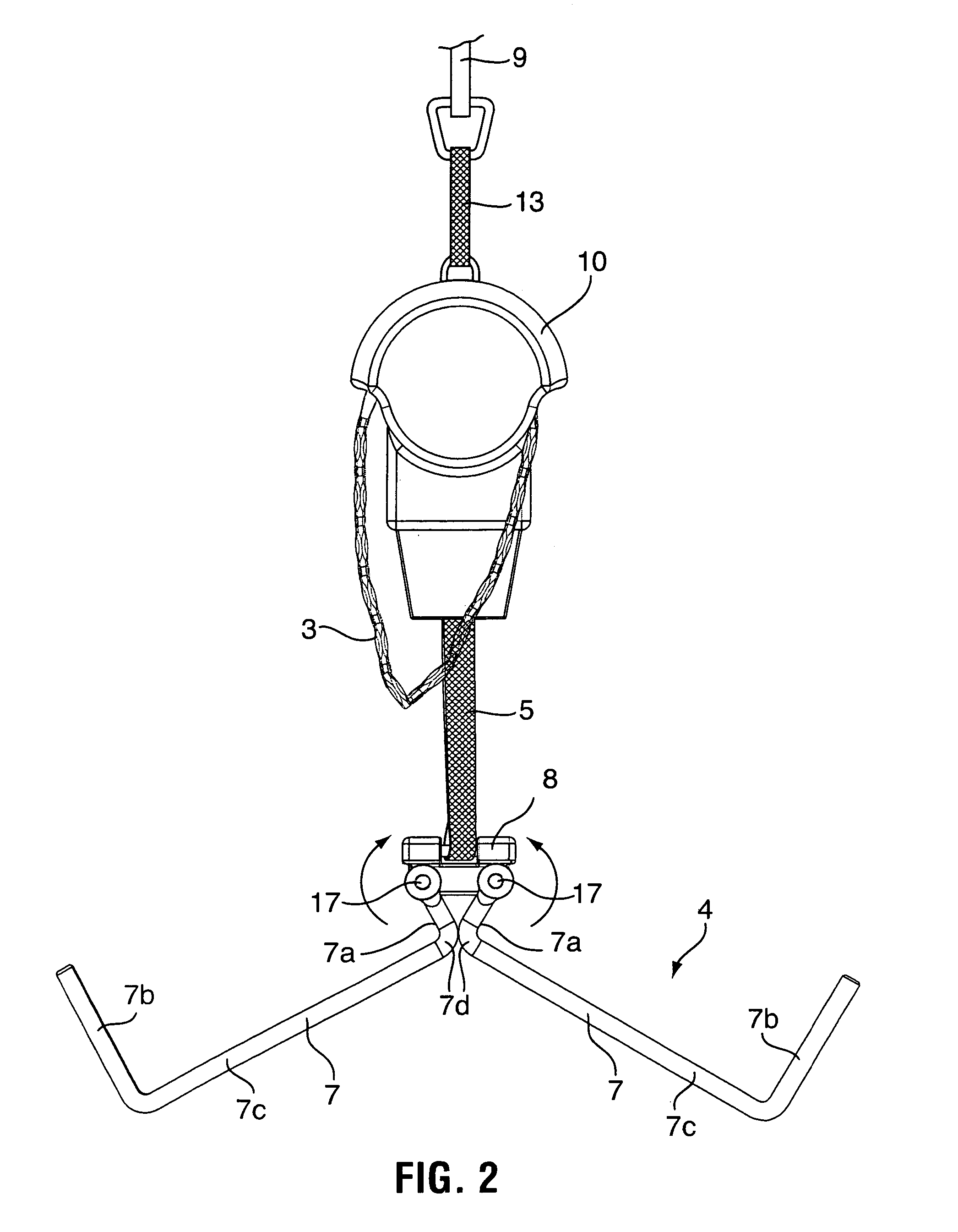
[0012]The arms preferably have elongated sections between the proximal and distal end sections, and the distal end sections are preferably oriented at an angle (e.g. in the range of 45 to 135 degrees, and more preferably 90 degrees) to the elongated sections, thereby forming upward projections from the elongated sections when the arms are in the operating position. This provides hook-like elements to prevent patient carrying arrangements from slipping off the arms. The arms preferably have elongated sections between the proximal and distal end sections, and the proximal end sections are preferably orientated at an angle to the elongated sections, thereby forming upward projections from the elongated sections when the arms are in the operating position. Also, the arms preferably have elbow sections where the proximal end sections join the elongated sections, and wherein the elbow sections abut against each other when the arms are in the operating position, thereby preventing downward pivotal motion of the arms.
[0018]The links of one of the two kinds may be provided with re-entrant sections at each longitudinal end, and wherein the links of the other of the two kinds are elongated and have opposed ends shaped and dimensioned to fit within the re-entrant sections of the links of the one kind. Adjacent links may then be mutually pivotally attached by bosses or pins extending between the links within the re-entrant sections. The links of the other kind are shaped such that two links of the one kind attached at opposite ends of a link of the other kind are enabled to pivot into mutual contact without causing detachment of the pins or permanent deformation of the links.
[0019]The raising and lowering mechanism preferably includes a one-way roller bearing for an axle and an axle journaled in the bearing, the bearing allowing mutual rotation between the bearing and the axle in one direction consistent with raising of the load, but preventing mutual rotation in an opposite direction consistent with lowering of the load, thereby enabling the load to be raised to any desired elevation by operation of the raising and lowering mechanism and held at the elevation without lowering upon ceasing operation of the raising and lowering mechanism. The raising and lowering mechanism preferably also includes a magnetic clutch that prevents overload of the raising and lowering mechanism.
[0020]According to another aspect of the invention, there is provided a raising and lowering device provided with a raising and lowering mechanism, an attachment element adapted to enable the device to be suspended from an elevated support, a load-carrying support adapted to support a load to be raised or lowered by the mechanism, a drive input for the mechanism and a magnetic clutch between the drive input and the mechanism, the magnetic clutch being adapted to isolate the mechanism from the drive input when a load of more than a predetermined weight is carried by the load-carrying support and lifting of the weight is attempted. Ideally, the magnetic clutch comprises a pair of elements that are rotatable independently of each other, the elements having confronting parts that are mutually magnetically attractive, one of the elements being operably connected to the drive input and the other of the elements being operably connected to the raising and lowering mechanism. These elements may be provided with depressions containing magnets forming the confronting parts. The elements are normally rotatable about aligned axes and the magnets are positioned around each element at substantially equal distances from the axes and the elements may be separated by a spacer element that facilitates mutual rotation of the plates when lifting of the weight is attempted.

Problems solved by technology

However, the provision of an elongated spreader bar makes the device rather bulky and awkward when it has to be transported from on point of use to another, or merely stored.
Moreover, devices provided with electric motors, while convenient, are rather heavy and therefore difficult to transport.
Furthermore, the raising and lowering mechanisms of such devices often include ratchet-like mechanisms (ratchet and pawl arrangements) to hold the patient securely in an elevated position.
However, such mechanisms are noisy and can be annoying or disturbing to patients and operators alike.

Method used


Image

  • Portable raising and lowering device and equipment therefor
  • Portable raising and lowering device and equipment therefor
  • Portable raising and lowering device and equipment therefor

Examples


Embodiment Construction

General Description

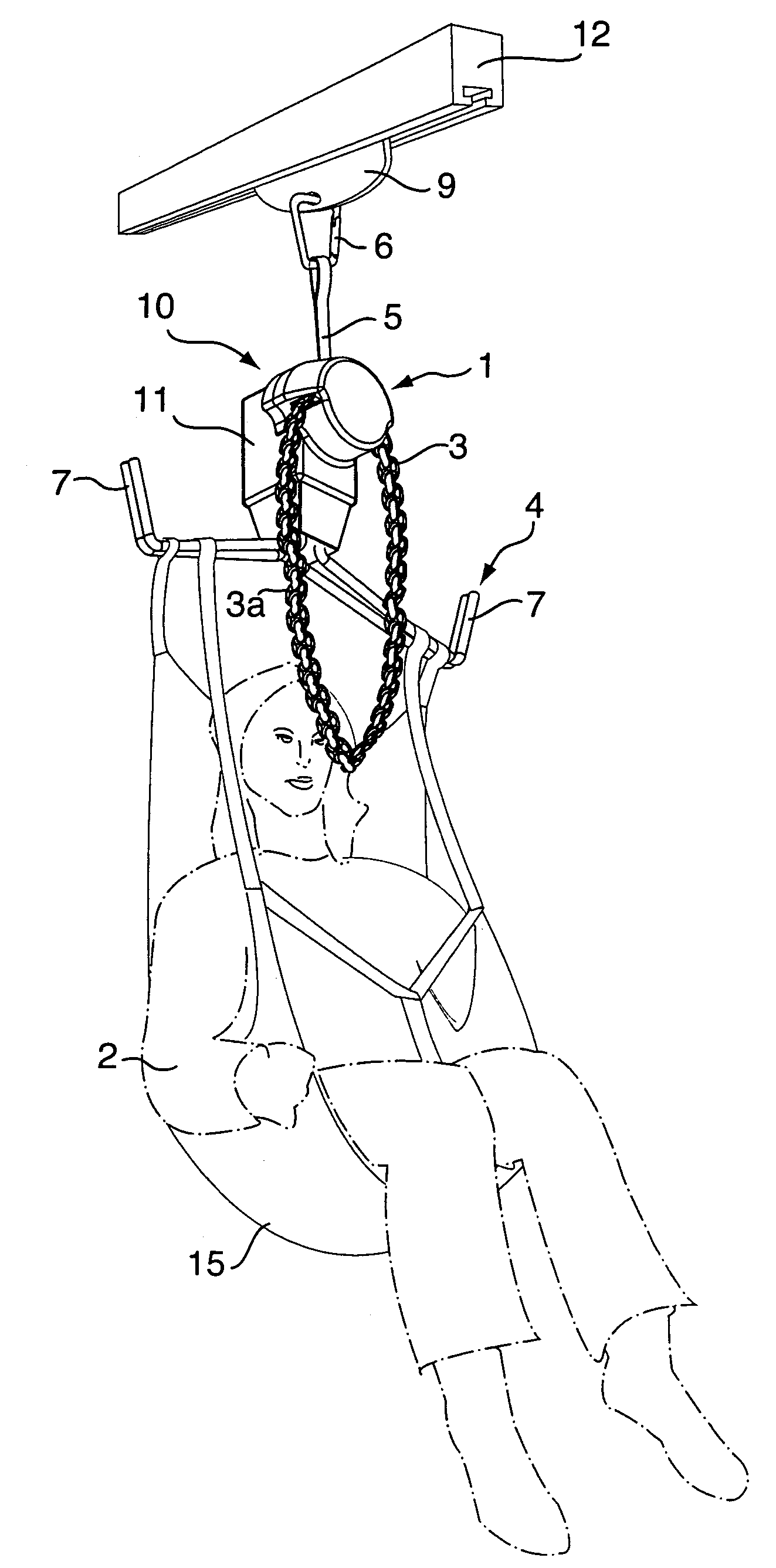
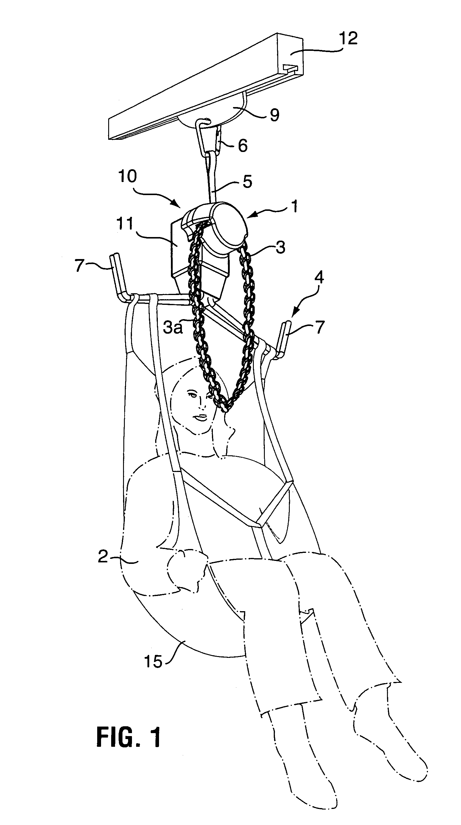
[0045]As shown in FIG. 1 of the accompanying drawings, one form of the present invention comprises a raising and lowering device 10 for a human patient 2. The device 10 is provided with a housing 11 (forming a casing enclosing a raising and lowering mechanism), a flexible elongated member 5, such as a strong flexible but inextensible webbing strap, belt or band, extending from the housing 11 and secured at an opposite (upper) end to an attachment element 6, such as a hook having a releasable locking tongue, that suspends the device from a slider 9 movable in an elevated fixed track 12. The flexible elongated member 5 can be wound and unwound about a reel component forming part of the raising and lowering mechanism within the housing 11 of the device 10 and is configured such that the induced rotation of the reel component by a drive input in one direction or the other leads to the raising or lowering of the housing 11. The drive input may be manually powered by me...


PUM


Abstract

A raising and lowering device, particularly suitable for incapacitated human or animal patients. The device includes a load carrying support having at least one elongated arm including a proximal end section and distal end section. The arm is pivotable on the device at the proximal end section and movable by pivoting between an operating position in which the support is positioned for carrying said load, and a stored position in which the arm forms a graspable handle allowing an operator to carry the device. The invention also relates to components suitable for use with the device.

Description

CROSS-REFERENCE TO RELATED APPLICATION[0001]This application is related to commonly-owned now abandoned, U.S. provisional patent application Ser. No. 60 / 448,564, filed Feb. 18, 2003, and claims the benefit of the earlier filing date of this application under 35 U.S.C. § 119(e).FIELD OF THE INVENTION[0002]This invention relates to portable raising and lowering devices often referred to as hoists, winches or lifts. More particularly, although not exclusively, the invention relates to such devices intended for lifting and optionally transporting human or animal patients who are temporarily or permanently incapacitated. The invention also relates to equipment used as parts of, or for operation of, such devices.DESCRIPTION OF THE PRIOR ART[0003]The present invention relates to raising and lowering devices of all kinds, but it is especially suitable for use in medical or patient care settings for raising and lowering human or animal patients. For the sake of convenience, the invention wil...

Claims


Application Information

Patent Timeline
IPC IPC(8): B66D1/26A61G5/00B66C19/00A61G7/10B66D3/16B66D3/26
CPCA61G7/1015A61G7/1042A61G7/1051B66D3/26B66D3/16A61G7/1069A61G2200/34A61G7/1061
Inventor KEANE, BRIANBELLAIRE, THOMAS L.JANZEN, ERNIEKANIGAN, RYAN WILLIAMMATTIE, JOHANNEPARIS-SEELEY, NANCY JOANWILSON, COLIN
Owner BRITISH COLUMBIA INSTITUTE OF TECHNOLOGY
Learn More