
Autofocus actuator

a technology of actuators and actuator parts, applied in the direction of camera focusing arrangement, printers, instruments, etc., can solve the problems of increasing the number of actuator parts, reducing the yield rate or productivity of springs, and increasing the manufacturing cost of springs, so as to facilitate the alignment and assembly of permanent magnets

Active Publication Date: 2007-10-23
MITSUMI ELECTRIC CO LTD
View PDF8 Cites 81 Cited by
  • Summary
  • Abstract
  • Description
  • Claims
  • Application Information

AI Technical Summary

Benefits of technology

The present invention provides an autofocus actuator with a yoke that allows for easier alignment and assembly of permanent magnets. The yoke includes a plurality of permanent magnets that interact with a coil to adjust the position of a lens in an optical axis direction. The permanent magnets are flat plate shape, which reduces the cost of parts. The yoke has inner and outer cylindrical portions with magnet mounting surfaces, and the flat plate shape permanent magnets are disposed on the magnet mounting surfaces. The inner cylindrical portion has four corner portions that serve as positioning surfaces for easy alignment of the magnets. The outer cylindrical portion has four inner surfaces that define the magnet mounting surfaces, and the flat plate shape permanent magnets are disposed on the magnet mounting surfaces. The direction of the magnetic field is generally orthogonal to the direction of the electric current flowing through the coil, which increases the magnitude of the driving force of the holder in the optical axis direction. The outer cylindrical portion can have a cylindrical shape with four inner surfaces that define the magnet mounting surfaces, or a hexagonal cross-section with six inner surfaces that define the magnet mounting surfaces. These features make it easy to align the permanent magnets and achieve a sufficient magnetic field for effective autofocus.

Problems solved by technology

A need of such bending process reduces the yield rate or productivity of the springs.
This poses a drawback in that the number of parts of the actuator is increased.
Moreover, the front spring and the rear spring are of mutually different shape, which disadvantageously leads to an increased manufacturing cost of the springs.
However, the permanent magnets with such configuration are costly, thus the cost for the parts becomes higher.
In addition, the actuator referred to hereinabove requires the use of a gig or the like in the process of assembly to align the curved permanent magnets with respect to the yoke, thus making the assembly process troublesome.
Further, there is a need for providing a magnet support means or the like which can position the permanent magnets in advance into the yoke, which causes a problem in that the number of parts of the actuator is increased.

Method used


Image

  • Autofocus actuator
  • Autofocus actuator
  • Autofocus actuator

Examples


Embodiment Construction

[0042]An autofocus actuator proposed by the present inventor and used as the premise of the present invention will be first described in detail with reference to the drawings attached.

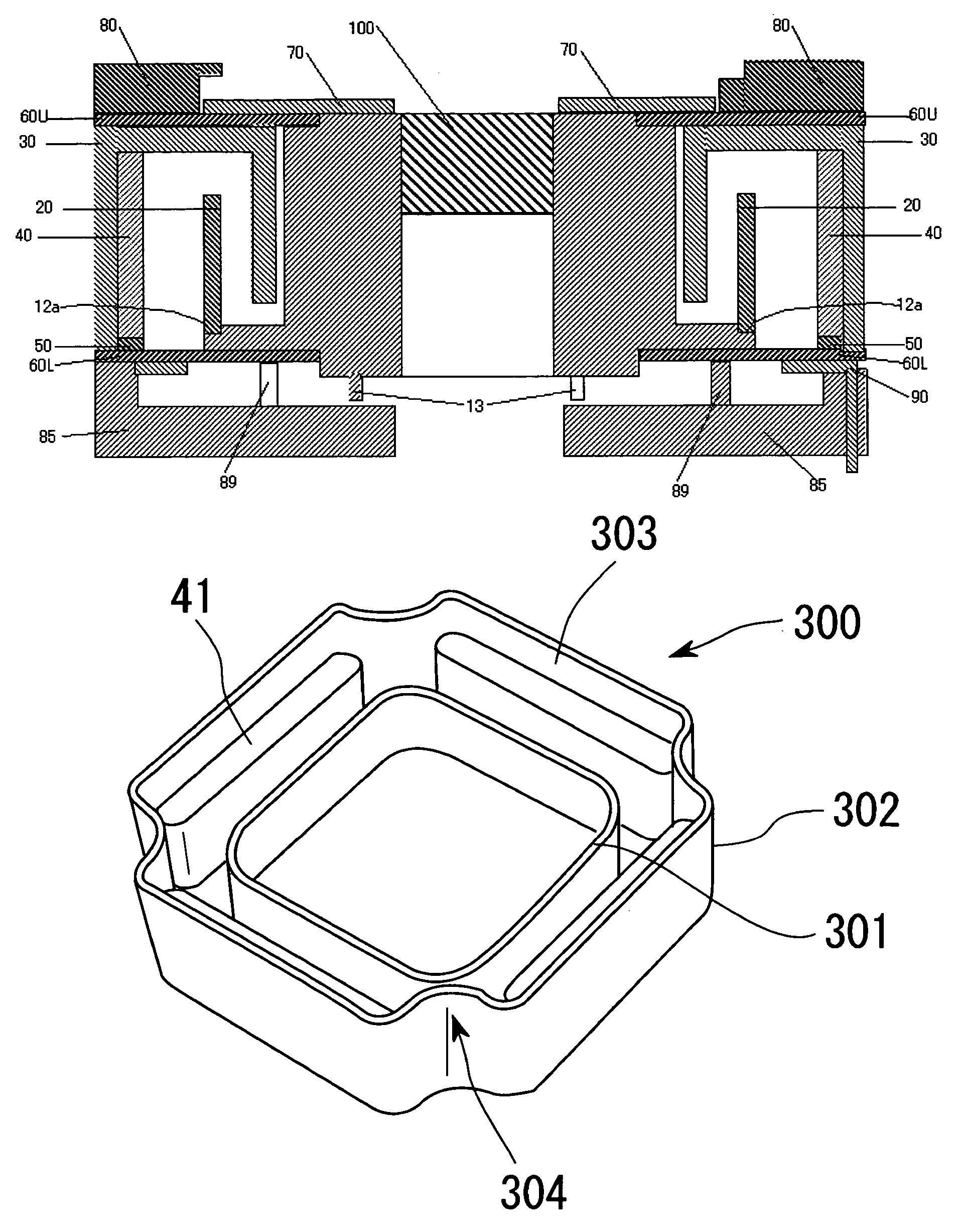
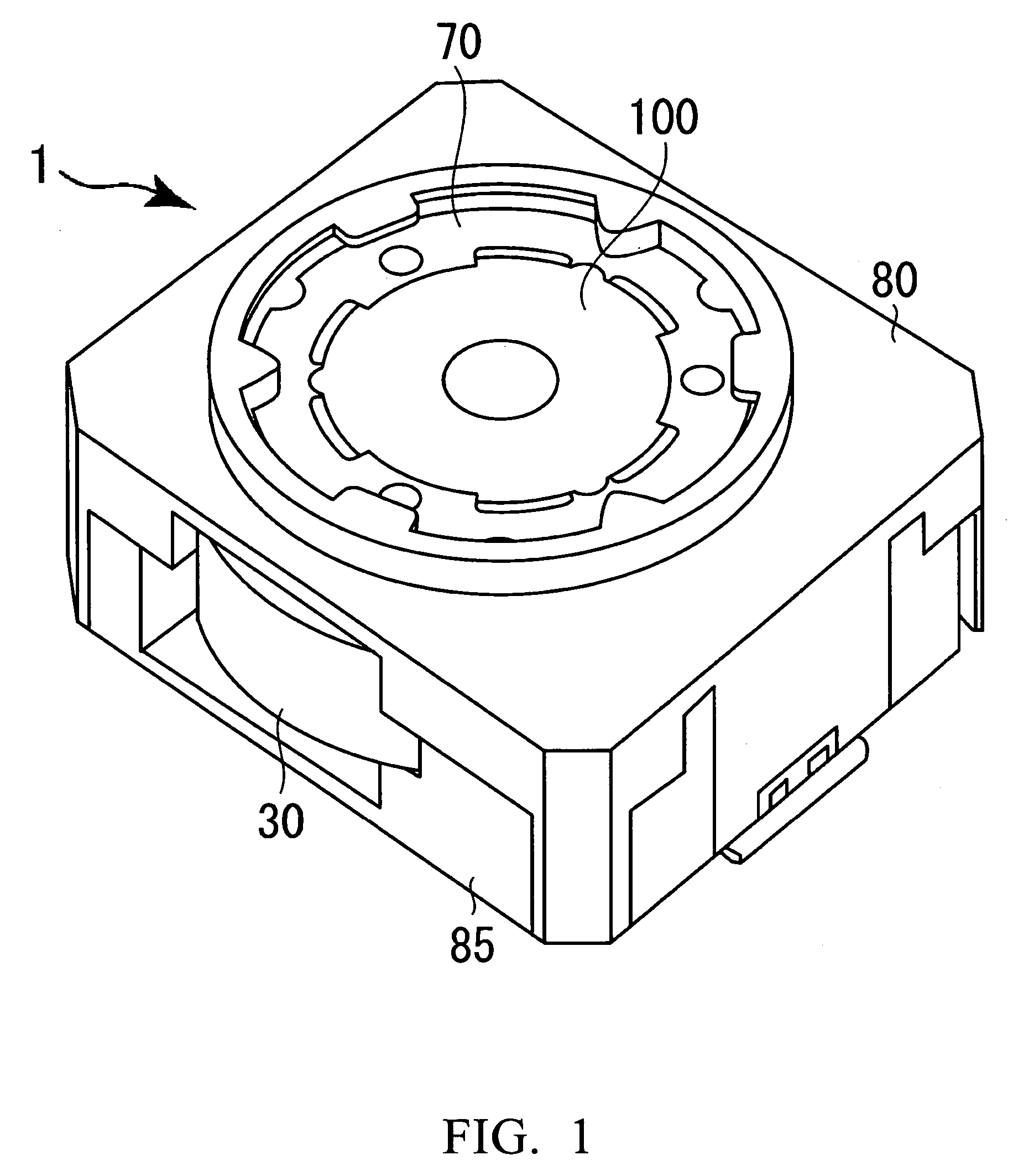
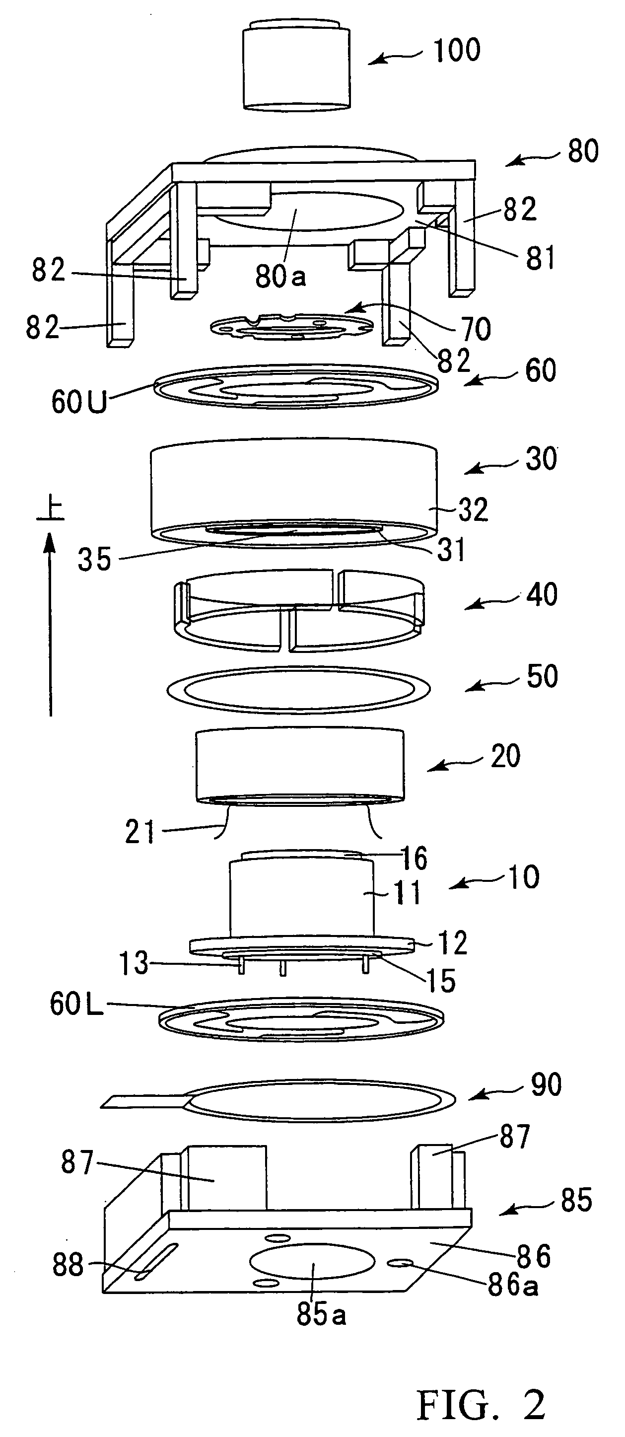
[0043]Referring to FIG. 1, there is shown perspective view showing the external appearance of the autofocus actuator. FIG. 2 is an exploded perspective view of the autofocus actuator shown in FIG. 1. FIG. 3 is a schematic cross-sectional view of the autofocus actuator shown in FIG. 1.

[0044]As shown in FIGS. 1, 2 and 3, the autofocus actuator 1, simply referred to as “actuator” hereinbelow, is generally composed of: a holder 10 including a hollow body portion 11 having one end to which a lens assembly 100 is attached, and a flange portion 12 provided along the perimeter of the other end of the hollow body portion 11; a coil 20 fixedly secured to the holder 10 in a spaced-apart relationship with the outer circumference of the hollow body portion 11; a cylindrical yoke 30 including an inner cylindrical po...


PUM

PropertyMeasurementUnit
magnetic fieldaaaaaaaaaa
resilient forceaaaaaaaaaa
yield rateaaaaaaaaaa

Abstract

An autofocus actuator 1 is provided with a yoke 300 that comprises an inner cylindrical portion 301 defining an insertion bore through which a hollow body portion of a holder is adapted to be received and an outer cylindrical portion 302 provided outside of the inner cylindrical portion 301 with a predetermined spacing left between the inner cylindrical portion 301 and the outer cylindrical portion 302 by a connecting portion, and the yoke 300 is constructed so as to receive a coil 20 in the space of a predetermined gap. The outer cylindrical portion 302 is formed into a generally polygonal cylindrical shape and inner surfaces of the outer cylindrical portion 302 define a plurality of magnet mounting surfaces each having a planar shape. A generally flat plate shape permanent magnet 41 is mounted on each of these magnet mounting surfaces 303. By the use of such a flat plate shape permanent magnet 41, it becomes possible to reduce a manufacturing cost and also possible to easily align and assemble the permanent magnets 41.

Description

BACKGROUND OF THE INVENTION[0001]1. Field of the Invention[0002]The present invention relates to an autofocus actuator, and more specifically to an autofocus actuator that can be employed in digital cameras or other small-sized electronic apparatuses equipped with a camera, e.g., cellular phones.[0003]2. Description of the Related Art[0004]In digital cameras, an actuator that can displace a lens in an optical axis direction is employed for the sake of autofocusing and zooming operations. This type of actuator is adapted to displace the lens in the optical axis direction by virtue of an interaction between the magnetic field generated by the electricity flowing through a coil and the magnetic field of a permanent magnet. In recent years, a need exists for the function of autofocus even in a camera mounted to cellular phones, because the number of pixels of a picture-taking element for use in the cellular phone camera tends to increase up to the order of mega pixels greater than one m...

Claims


Application Information

Patent Timeline
Patent Type & Authority Patents(United States)
IPC IPC(8): H02K41/00G11B11/00G11B7/00
CPCG02B7/08H04N5/2254G03B13/36G03B3/10
Inventor OSAKA, TOMOHIKO
Owner MITSUMI ELECTRIC CO LTD
Learn More