
Printer or other automatic printing system with additional control device and control device therefor

a printing system and control device technology, applied in the field of printing systems, can solve the problems of data transmission lines being practically cut off, data transmission lines being completely blocked or even physically cut, and ineffective ink reservoir refilling,

Inactive Publication Date: 2007-10-23
J S STAEDTLER
View PDF4 Cites 9 Cited by
  • Summary
  • Abstract
  • Description
  • Claims
  • Application Information

AI Technical Summary

Benefits of technology

[0010]It is an object of the present invention to configure printers or other automatic printing systems such as inkjet, drop on demand, or continuous inkjet printers such that the operator in a simple and easy way is enabled to employ even a refilled or other ink reservoirs or optionally other replacement parts.
[0013]With the solution according to the invention the already present material such as empty reservoirs, hose systems or other disposable parts can be optionally recycled (reused) which protects resources by means of less waste being produced and generally saves the user significant costs.

Problems solved by technology

A disadvantage of such a system is that the corresponding memory chip of the ink reservoir is provided, generally only one time, with printing data by the electronic device of the printer and that the electronic device then sends to the memory chip at a certain point in time a locking command in order to interrupt the printing process.
A chip which has been written on in this way then makes the ink reservoir useless so that it must be replaced with a new reservoir with a blank chip.
A further use by refilling of the empty ink reservoir is not possible because the chip is blocked (usually irreversibly) and sends the signalcartridge empty” to the printer.
In this connection, the data transmission lines are practically cut off, completely blocked or even physically cut.
A disadvantage of such a system is however that usually all data lines, for example, also for the information of the fill level which are transmitted from the printer to the ink reservoir and vice versa, are completely blocked.
This “frozen information” thus does not provide actual fill level data of the ink reservoir and thus also does not provide a warning—actually required—that a low or critical ink level is present in the reservoir.
This process is not only time-consuming but also requires a significant experience and expertise in regard to handling and know-how for determining the actual ink contents.
This can cause leakage, contact errors and / or transmission failure.
Important is the information in regard to the ink fill level because when the reservoir is empty the correlated print head can possibly be irreversibly damaged.
Moreover, in such a case, it cannot be completely excluded that despite the replacement of a defective print head with a new one further problems occur because air can have entered the hose arrangement of the ink supply, and the destruction of the replacement print head is thus preprogrammed.
This not only causes a printer or production downtime for several days but in addition costly expenses for service and maintenance.
Each change, for example, of the ink reservoir requires the user to buy and dispose of a complete ink reservoir, i.e., in addition to the required ink also a housing, an ink bag, valves, electronic devices and so on, even though the hardware elements generally are still usable and could be used multiple times without causing problems.

Method used


Image

  • Printer or other automatic printing system with additional control device and control device therefor
  • Printer or other automatic printing system with additional control device and control device therefor

Examples


Embodiment Construction

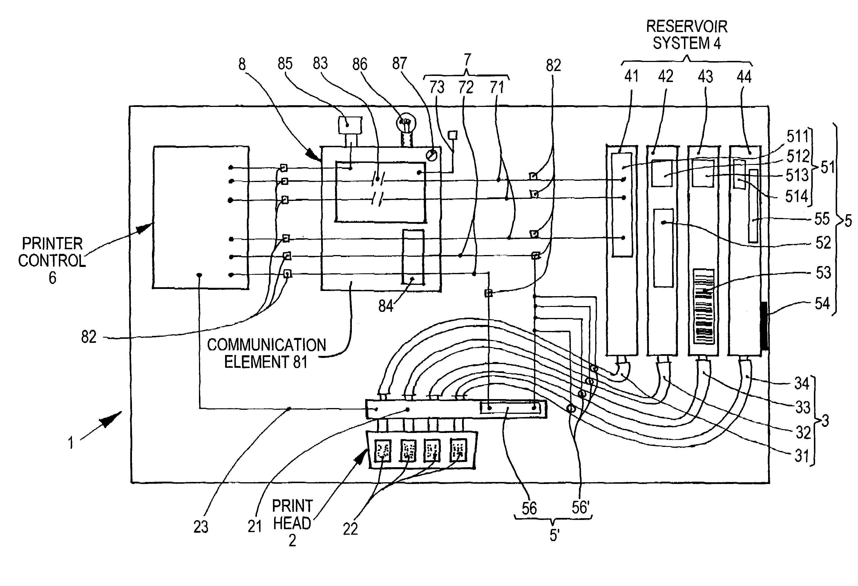
[0017]A suggested control device, as a communication system 8, which is configured as a communication element 81 and is connected in the data lines 7 between the electronic device 6 of the printer and the reservoir system 4 will be explained in the following in more detail. The only FIGURE shows a printer or printing system having a control device in the form of a communication system 8 connected in the data line 7 between the electronic device 6 of the printer and the memory chip 51, 511, 512, 513, 514 etc. of the ink reservoirs 41, 42, 43, 44 etc. correlated with these data lines 71. It should be noted that for reasons of simplifying the drawing only a limited date line 7 as a chip line 71 is provided between the electronic device 6 of the printer and the ink reservoir 41 and a further one as a hose connection 72 to the hose system 3 and to the print head slide 21. Other reading devices, sensors, scanners for optical fields 52, EAN coding 52, fill level meters 54, reservoir identi...


PUM


Abstract

A printing system has at least one print head, a refillable or exchangeable ink reservoir or reservoir system, an electronic device for printing, a communication system as a control device for transmitting, blocking, and processing different signals, pulses, information, and data. The communication system is connected to the electronic device for printing and the ink reservoir or the reservoir system.

Description

BACKGROUND OF THE INVENTION[0001]1. Field of the Invention[0002]The invention relates to a printer or other printing system, in particular, for automatic recording, writing or drawing devices or output devices for electronic data processing devices, preferably as an inkjet, drop on demand or continuous jet printer or printing system with at least one control device, a print head, an electronic device for printing, and a refillable and / or exchangeable ink reservoir or reservoir system. The invention further relates to a control device for the printer or printing system.[0003]2. Description of the Related Art[0004]Printers or printing systems comprising at least one print head, an electronic device for printing and further comprising an ink reservoir or reservoir system are already known from German patent application 199 56 702 A1 and European patent application 1 180 912 A1. The exchangeable ink reservoirs are provided with memory chips as coding systems which contains certain basic...

Claims


Application Information

Patent Timeline
IPC IPC(8): G06F15/00G06F3/12B41J2/175
CPCB41J2/17546B41J2/17509
Inventor ENGEL, STEFAN
Owner J S STAEDTLER
Learn More