Laser diode bar beam reformatting prism array

a technology of laser diodes and prism arrays, applied in the field of high-power laser diodes arrays, can solve the problems of high energy loss, asymmetrical properties, high undesirable asymmetry, etc., and achieve the effects of avoiding interference, facilitating collimation of arrays and launching, and more symmetric properties

Inactive Publication Date: 2007-10-23
NORTHROP GRUMAN CORP
View PDF14 Cites 9 Cited by
  • Summary
  • Abstract
  • Description
  • Claims
  • Application Information

AI Technical Summary

Benefits of technology

[0008]The present invention resides in an optical prism structure for reformatting output from a laser diode bar, which normally produces an linear array of output beams with cross-sectional shapes that are elongated in the same direction as the linear array. The prism structure of the invention comprises an array of optical roof prisms, each of the prisms having two opposed triangular faces, a hypotenuse face and two angled faces adjoining the hypotenuse face and adjoining each other to form a prism roof angle. The prisms in the array are positioned with common features arrayed along a selected axis, and are positioned with the triangular faces of adjacent prisms in overlapping contact. Each prism is offset from the closest adjacent prism by an offset distance equal to the thickness of each prism. This results in an array in which the roof line of each prism is oriented at 45° degrees to the selected axis. The array is positioned to receive light from a plurality of beams arrayed along the same selected axis and directed normal to the hypotenuse faces of the prisms. Each beam is internally reflected from a separate one of the prisms and, as a result of the orientation of the prisms, emerges with its cross-sectional shape rotated by 90°. The beam array is thereby reformatted to have more symmetric properties, which facilitate collimation of the array and launching into a fiber or other optical component.
[0009]Preferably, the optical prism structure further comprises an additional roof prism, having a length approximately co-extensive with the array of prisms measured along the selected axis, and positioned to receive light beams reflected from the array of prisms and to reflect the received beams as a set of parallel but oppositely directed beams. The additional roof prism directs the output light beams away from the laser diode bar, thereby avoiding any ancillary components needed for cooling and making electrical connections to the laser diodes.
[0010]It will be appreciated from the foregoing summary, that the invention provides a significant advance in the field of high power laser devices using laser diode bars. In particular, the invention provides a prism structure that reformats the output beams from a laser diode bar, to provide a desirable symmetric composite cross section for the beam array. The use of an additional roof prism directs the output beam array away from the laser diode bar and avoids interference between the output beams and laser diode bar ancillary equipment. Other aspects and advantages of the invention will become apparent from the following more detailed description, taken in conjunction with the accompanying drawings.

Problems solved by technology

A laser diode bar structure has a significant disadvantage in that light emitted from the structure consists of multiple relatively wide emitting stripes arrayed along a straight line.
These asymmetrical properties are highly undesirable for most applications, including supplying pump power to a fiber laser.
Various solutions have been proposed to address the asymmetry of output from a laser diode array, such as using twisted cylindrical lenses or multiply faceted mirrors, but all have potential disadvantages, such as having inherent energy losses or being difficult to manufacture.
Unfortunately, neither of these proposed solutions is completely satisfactory.
The need for two sets of roof prisms as proposed in the Wang paper results in higher cost and potential alignment difficulties.
The use of mirrors as proposed in the Xiao patent application potentially results in higher energy losses and manufacturing costs when compared with the use of prisms.

Method used


Image

  • Laser diode bar beam reformatting prism array
  • Laser diode bar beam reformatting prism array
  • Laser diode bar beam reformatting prism array

Examples


Embodiment Construction

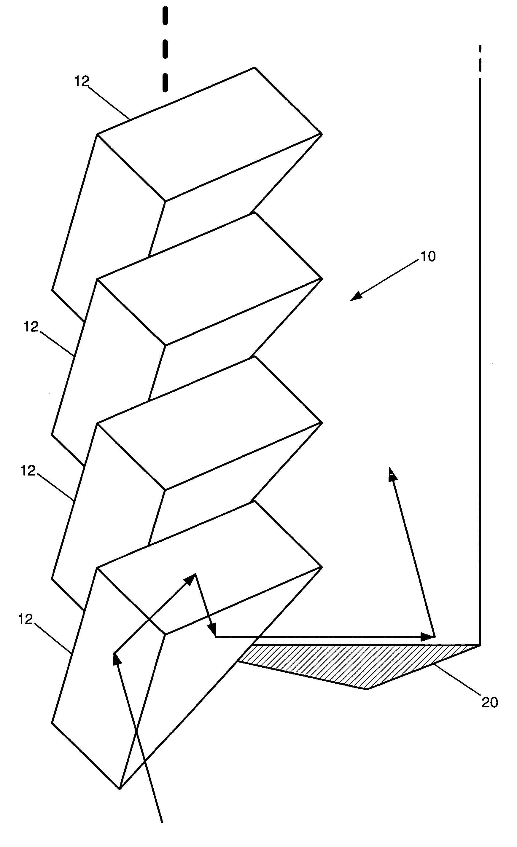
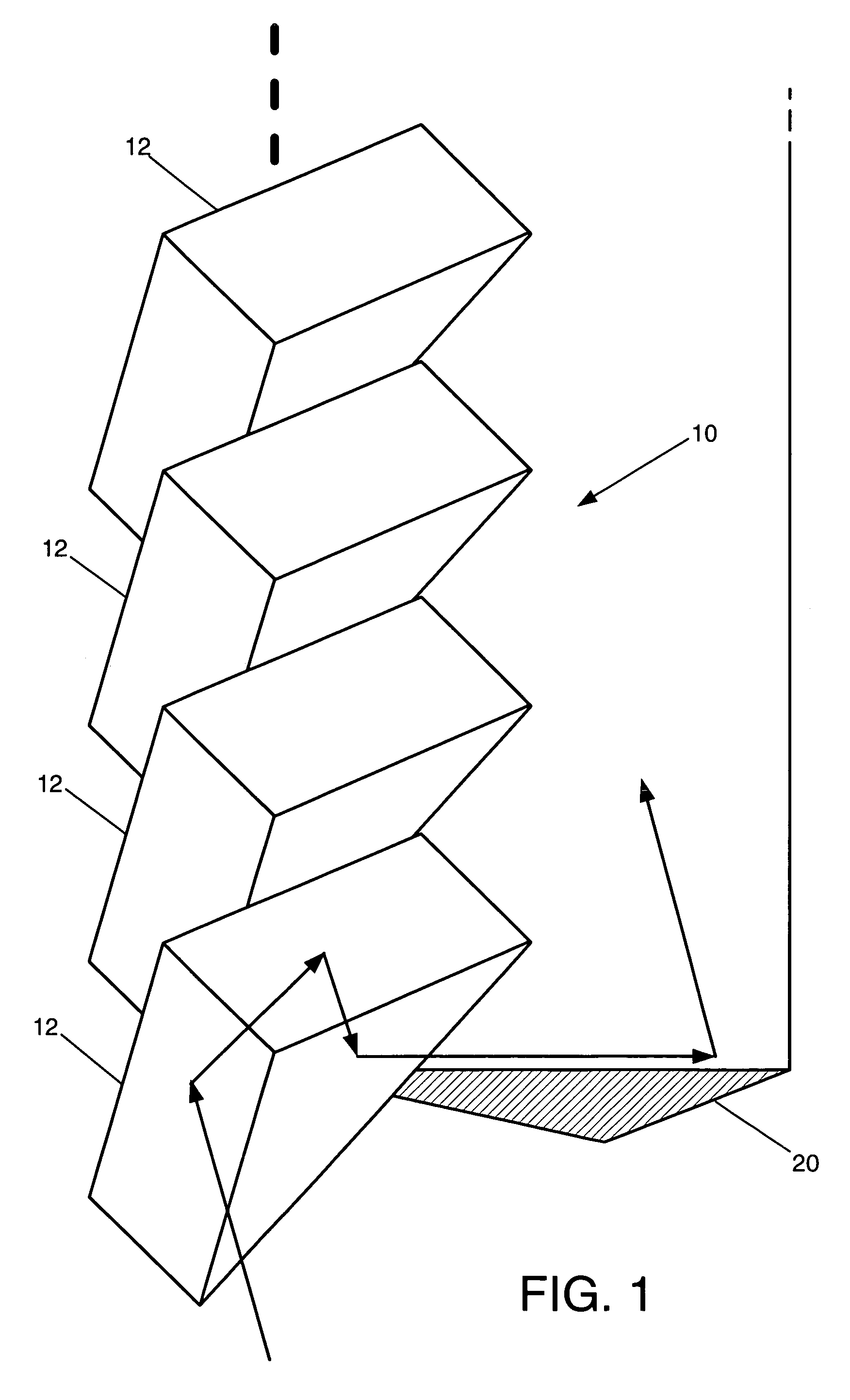
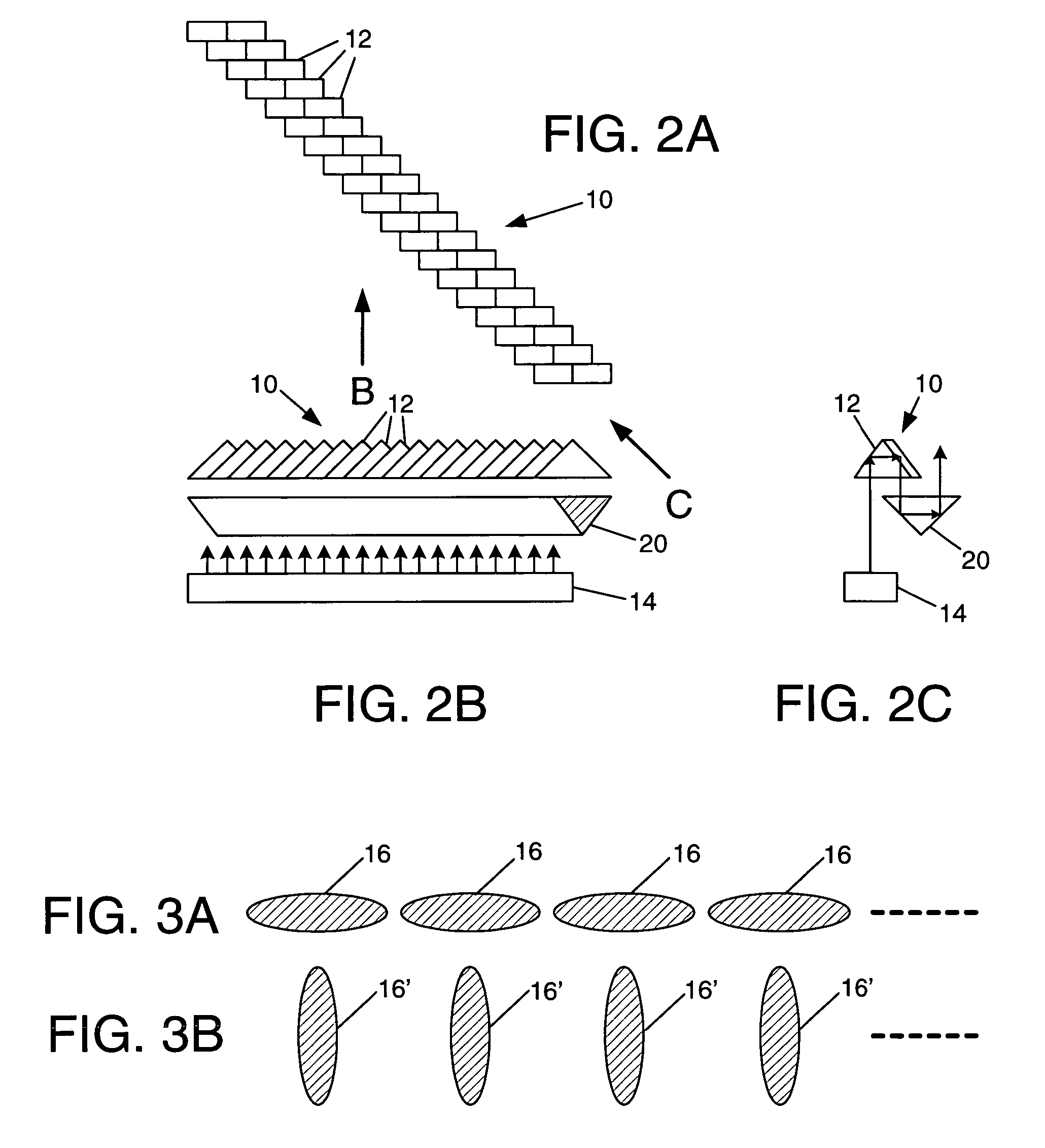
[0017]As shown in the drawings for purposes of illustration, the present invention pertains to a technique for reshaping or reformatting an output beam from a laser diode bar array of the type that may be used in high power applications, such as for pumping a fiber laser. A well known difficulty associated with laser diode bar arrays of wide stripe emitters is that the resultant output beam is elliptical in cross section and diverges differently in the transverse and lateral directions. The output beam is said to exhibit anamorphism, as often defined by the beam invariant, which is the product of the near field diameter (in millimeters) and the far field diameter (in milliradians). Ideally, the beam invariant in the transverse and lateral directions should be roughly the same, meaning that the beam exhibits low astigmatism and a high degree of circularity of cross section. In this context, the “lateral” direction extends across the emitter array, parallel to the linear array of emit...


PUM


Abstract

Asymmetry of output beams from a laser diode bar is significantly reduced by internally reflecting the beams from an array of roof prisms positioned and oriented to rotate the cross-sectional shape of each beam by 90°. An elongated retro prism is positioned to received all of the reflected beams and to redirect them away from the laser diode bar.

Description

BACKGROUND OF THE INVENTION[0001]This invention relates generally to laser diode arrays and, more particularly, to high power laser diode arrays used for pumping fiber lasers. Optical fiber lasers are often employed as components in high power laser systems and, in a typical configuration of a fiber laser, an array of laser diodes is used for optically pumping the fiber laser. Such arrays are often referred to as laser diode bars.[0002]A laser diode bar structure has a significant disadvantage in that light emitted from the structure consists of multiple relatively wide emitting stripes arrayed along a straight line. For example, each emitting segment may be approximately 1 μm×3.5 μm in cross section. A typical array may have an emitting surface with about nineteen or twenty segments, with an overall width of about 1.0 cm and with each segment only 1 μm in height. Therefore, the output beam from the laser diode array is highly asymmetrical. The raw, unfocused output beam is highly d...

Claims


Application Information

Patent Timeline
Patent Type & Authority Patents(United States)
IPC IPC(8): G02B5/04G02B27/09
CPCG02B27/0972G02B19/0028G02B19/0057
Inventor KENNEDY, CHANDLER J.
Owner NORTHROP GRUMAN CORP
Why Eureka
Try Eureka