Secure document design carrying auxiliary machine readable information
Inactive Publication Date: 2007-10-23
DIGIMARC CORP (FORMERLY DMRC CORP)
View PDF156 Cites 71 Cited by
Summary
Abstract
Description
Claims
Application Information
AI Technical Summary
This helps you quickly interpret patents by identifying the three key elements:
Problems solved by technology
Method used
Benefits of technology
[0016]In some embodiments, security documents are encoded to convey machine-readable multi-bit binary information (e.g., digital watermarks), usually in a manner not alerting human viewers that such information is present. The documents can be provided with overt or subliminal calibration patterns. When a document incorporating such a pattern is scanned (e.g., by a photocopier), the pattern facilitates detection of the encoded information notwithstanding possible scaling or rotation of the scan data. The calibration pattern can serve as a carrier for the watermark information, or the watermark can be encod
Problems solved by technology
Common counterfeiting techniques—e.g., color photocopying, or scanning/inkjet
Method used
Image
Click on the blue label to locate the original text in one second.
Reading with bidirectional positioning of images and text.
Examples
Embodiment Construction
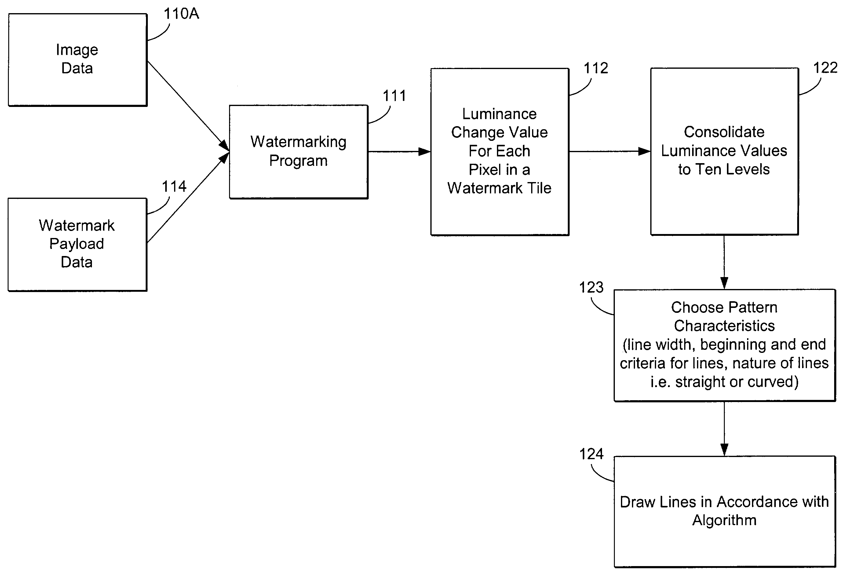
[0038]By way of introduction, this specification begins with review of techniques for embedding watermark data in line art, as disclosed in my application Ser. No. 09 / 074,034.
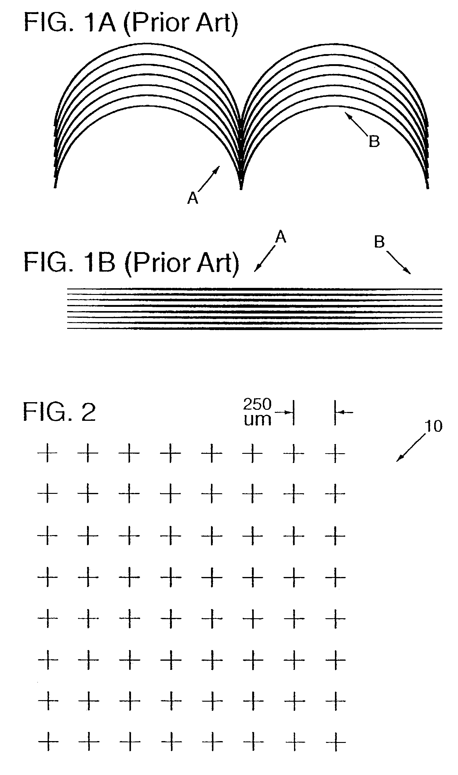
[0039]Referring to FIG. 2, the earlier-described technique employs a grid 10 of imaginary reference points arrayed over a line art image. The spacing between points is 250 microns in the illustrated arrangement, but greater or lesser spacings can of course be used.
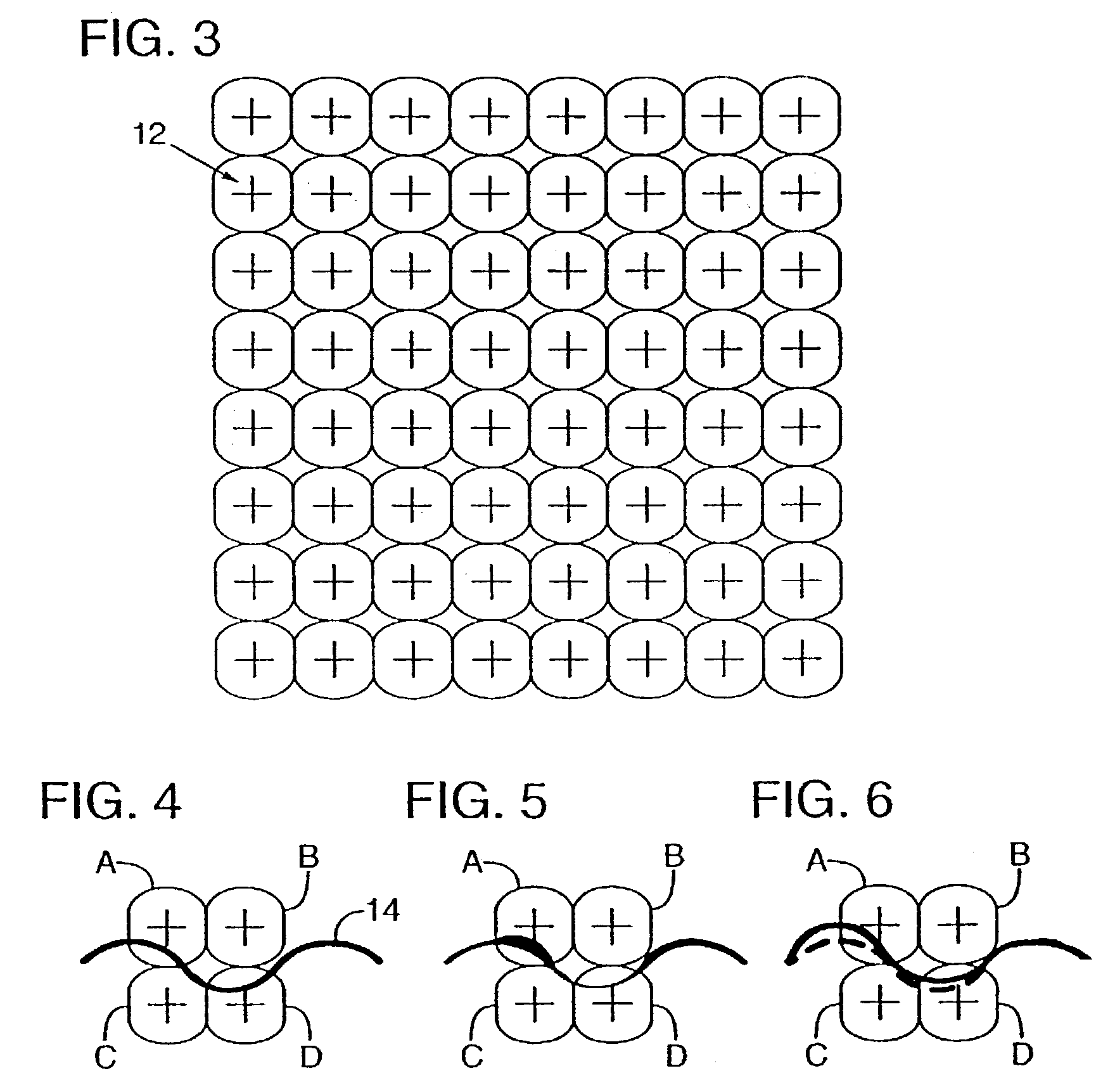
[0040]Associated with each grid point is a surrounding region 12, shown in FIG. 3. As described below, the luminosity (or reflectance) of each of these regions 12 is slightly changed to effect subliminal encoding of binary data.
[0041]Region 12 can take various shapes; the illustrated rounded-rectangular shape is representative only. (The illustrated shape has the advantage of encompassing a fairly large area while introducing fewer visual artifacts than, e.g., square regions.) In other embodiments, squares, rectangles, circles, ellipses, etc., can alt...
PUM
Property
Measurement
Unit
Length
aaaaa
aaaaa
Area
aaaaa
aaaaa
Luminance
aaaaa
aaaaa
Abstract
A two dimensional pattern design for secure documents serves as both a machine readable code and an aesthetic part of the documents' design. A method for generating the design generates a variable auxiliary message comprising message values and maps the message values to a two dimensional pattern of areas on the document. The areas each comprise an arrangement of pixels on the printed document. Depending on a value of the message mapped to a corresponding area, the method assigns a visible structure to the corresponding area. Different visible structures are assignable to a single value of the message to create a visible design having a desired aesthetic appearance.
Description
RELATED APPLICATION DATA[0001]This application is a continuation in part of application Ser. No. 09 / 939,298, filed Aug. 24, 2001 (now U.S. Pat. No. 6,804,379), which is a continuation of application Ser. No. 09 / 127,502, filed Jul. 31, 1998 (now U.S. Pat. No. 6,345,104), and which claims the benefit of provisional application 60 / 082,228, filed Apr. 16, 1998 (the specification of which is attached as Appendix A).[0002]This application is also a continuation in part of Ser. No. 09 / 553,112, filed Apr. 20, 2000 (now abandoned), which claims priority to provisional application 60 / 131,005, filed Apr. 22, 1999, which are hereby incorporated by reference.[0003]This application is also a continuation in part of Ser. No. 10 / 165,751, filed Jun. 6, 2002 (now U.S. Pat. No. 6,754,377), which is continuation of Ser. No. 09 / 074,034, filed May 6, 1998 (now U.S. Pat. No. 6,449,377), which is a continuation-in-part of application Ser. No. 08 / 438,159 (now U.S. Pat. No. 5,850,481), filed May 8, 1995, and...
Claims
Application Information
Patent Timeline
Application Date:The date an application was filed.
Publication Date:The date a patent or application was officially published.
First Publication Date:The earliest publication date of a patent with the same application number.
Issue Date:Publication date of the patent grant document.
PCT Entry Date:The Entry date of PCT National Phase.
Estimated Expiry Date:The statutory expiry date of a patent right according to the Patent Law, and it is the longest term of protection that the patent right can achieve without the termination of the patent right due to other reasons(Term extension factor has been taken into account ).
Invalid Date:Actual expiry date is based on effective date or publication date of legal transaction data of invalid patent.