Color image processing method, color image processor, color display, computer program for implementing the color image processing method

a color image and image processing technology, applied in the field of color display, computer programs implementing the color image processing methods, can solve the problems of unnatural image, method cannot use the saturation dynamic range in an efficient manner, and less efficient color reproducibility, etc., to achieve excellent color reproducibility

Inactive Publication Date: 2007-10-23
SHARP KK
View PDF20 Cites 14 Cited by
  • Summary
  • Abstract
  • Description
  • Claims
  • Application Information

AI Technical Summary

Benefits of technology

[0054]Moreover, according to the color display of the present invention, provision of the above-described color image processor for a transmission type color display which is more excellent in color reproducibi...

Problems solved by technology

On the other hand, for transmission type displays using liquid crystal or the like, which are less efficient in color reproducibility compared to CRTs, methods of improving color reproducibility have been proposed.
However, in the aforementioned method disclosed in Japanese Patent Application Laid-open Hei 5 No. 205039, areas with higher saturations are further enhanced, so that an image containing a high proportion of high saturation areas is reproduced as a whole with colors close to garish colors, resulting in an unnatural image.
In the method disclosed in Japanese Patent Application Laid-open Hei 8 No. 329217, since areas with low saturations and areas with high saturations are uniformly multiplied, the distribution of saturations is shifted as a whole to the higher saturation areas, hence this method cannot use the saturation dynamic range in an efficient manner.
On the other...

Method used


Image

  • Color image processing method, color image processor, color display, computer program for implementing the color image processing method
  • Color image processing method, color image processor, color display, computer program for implementing the color image processing method
  • Color image processing method, color image processor, color display, computer program for implementing the color image processing method

Examples


first embodiment

The first embodiment

[0079]To begin with, a color image processor and a color image processing method according to the first embodiment of the present invention will be described.

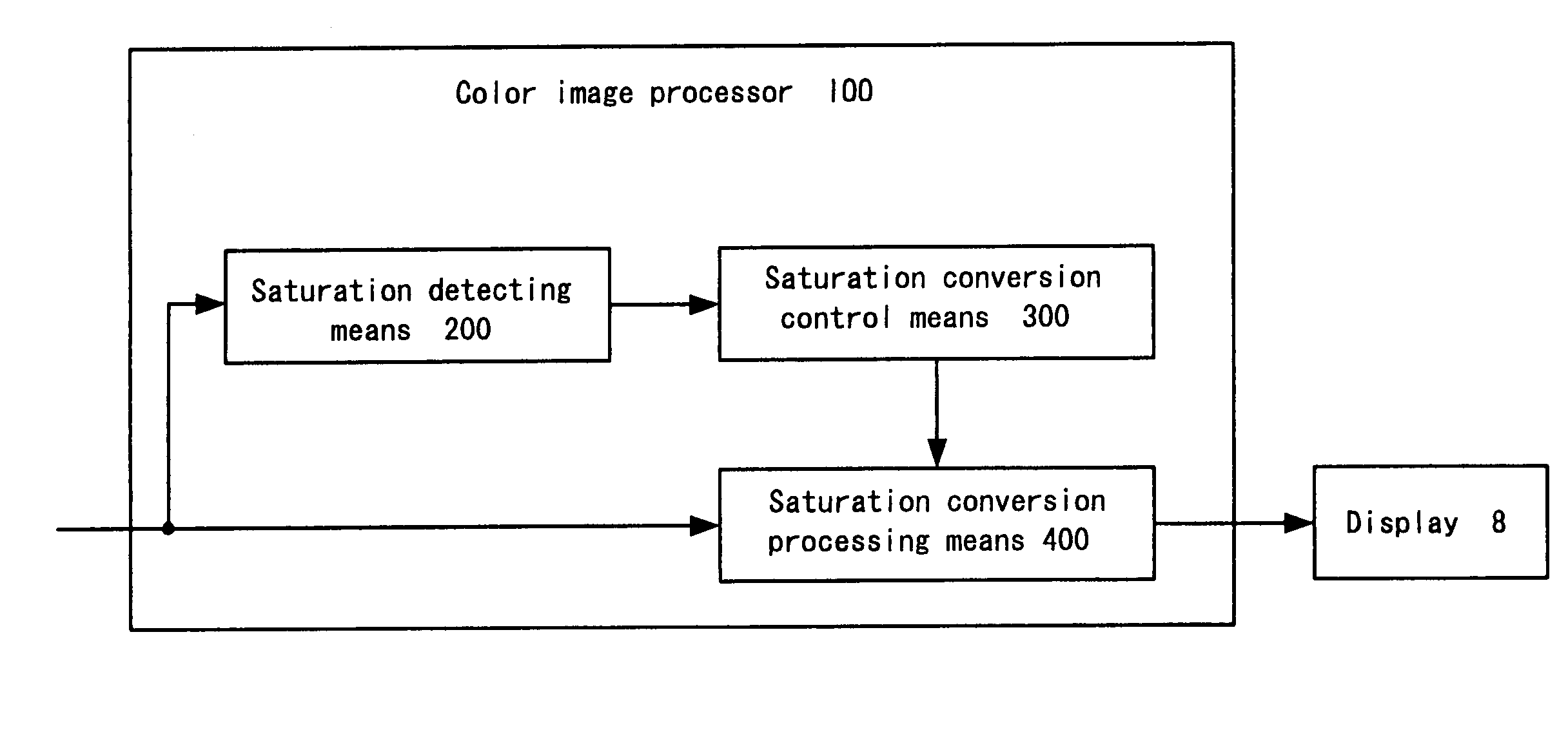
[0080]FIG. 6 is a block diagram showing an overall configuration of a color image processor according to the first embodiment of the present invention.

[0081]The color image processor 100 according to the first embodiment includes: as shown in FIG. 6, a saturation detecting means 200, a saturation conversion control means 300 and a saturation conversion processing means 400.

[0082]Saturation detecting means 200 detects the saturation C that is normalized by the following process, for example, from the RGB signal of an original color image, and outputs it.

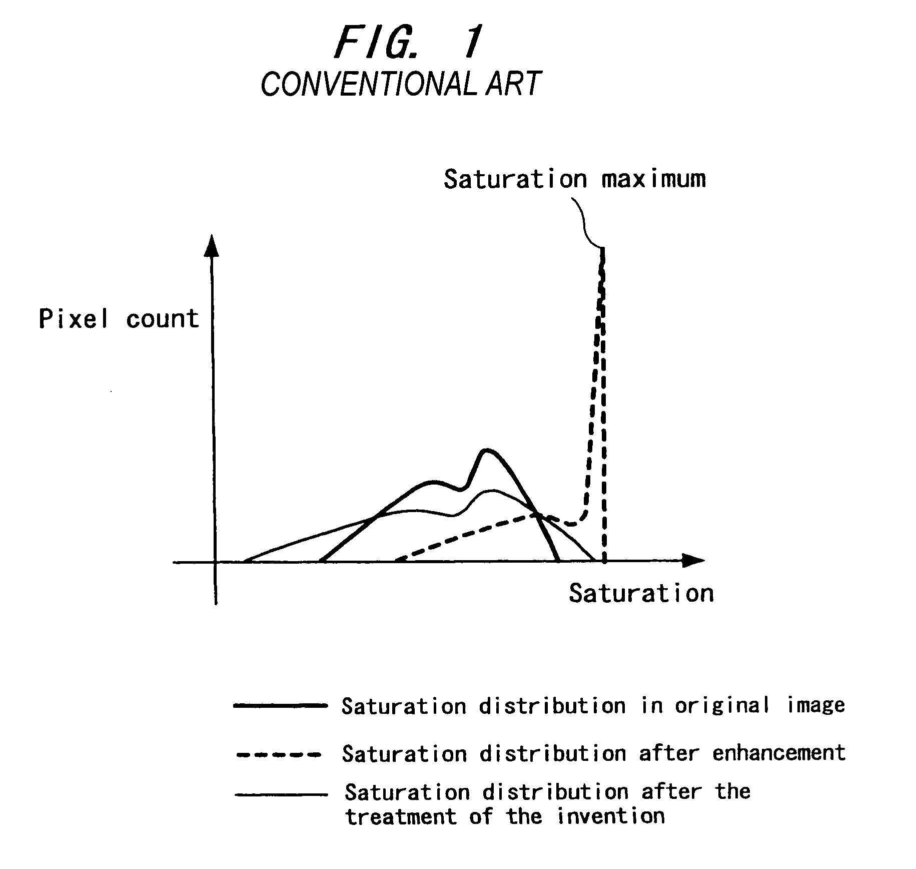
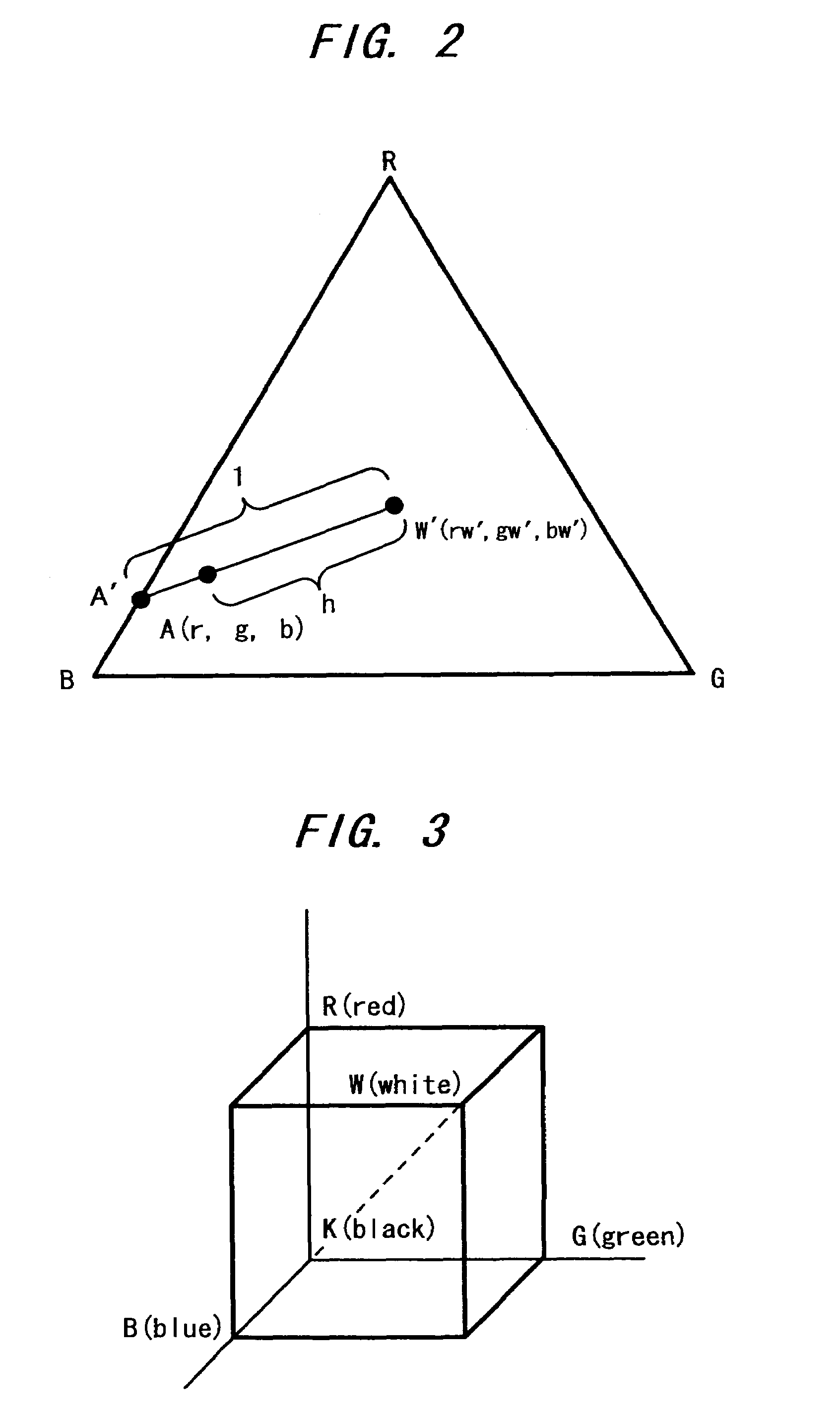
[0083]Specifically, for the RGB signal of an original color image, the saturation C in the 3-dimensional space defined along the axes of the three signals is considered. As shown in FIG. 3, in the displayable color range in the RGB space, achromatic colors, wh...

second embodiment

The second embodiment

[0105]Next, a color image processor and a color image processing method according to the second embodiment of the present invention will be described.

[0106]FIG. 16 is a block diagram showing an overall configuration of a color image processor according to the second embodiment of the present invention.

[0107]The color image processor 105 according to the second embodiment includes: as shown in FIG. 16, a saturation detecting means 200, a saturation conversion control means 302 and a saturation conversion processing means 400.

[0108]The saturation detecting means 200 and saturation conversion processing means 400 operate in the same manner as that of the first embodiment described with reference to FIG. 6.

[0109]Saturation conversion control means 302, based on the saturation C given from saturation detecting means 200 and a predetermined threshold α, calculates the value of saturation C′ after conversion and passes it to saturation conversion processing means 400. ...

third embodiment

The third embodiment

[0114]Next, a color image processor and a color image processing method according to the third embodiment of the present invention will be described.

[0115]FIG. 7 is a block diagram showing an overall configuration of a color image processor according to the third embodiment of the present invention.

[0116]The color image processor 101 according to the third embodiment includes: as shown in FIG. 7, a saturation detecting means 200, a saturation conversion control means 301, a saturation conversion processing means 400 and a threshold designating means 500.

[0117]The saturation detecting means 200 and saturation conversion processing means 400 operate in the same manner as that of the first embodiment described with reference to FIG. 6.

[0118]Threshold designating means 500 may be constituted of, for example, a dedicated numeral input device such as numeral keys, a multi-purpose input device such as PC keyboard. When the user inputs the desired threshold, the threshol...


PUM


Abstract

A saturation detecting means (200) detects saturation at every pixel in a digital color image or at every coordinate point in an analog color image. A saturation conversion control means (300) determines the saturation conversion condition for the pixel or coordinate point based on the detected saturation. A saturation conversion processing means (400) implements saturation conversion in such a manner that saturation is reduced for the areas with low saturations in the color image, so as to enlarge the difference in saturation relative to the areas with high saturations, thus achieving improved saturation contrast. Further, the distribution of saturations in the input image is automatically extracted, so as to determine the threshold for deciding a saturation suppressed area based on the distribution of saturations. In this way, in order to obtain a color image improved in vividness and presenting feeling of sharpness, the saturation contrast is automatically improved.

Description

[0001]This application is the national phase under 35 U.S.C. § 371 of PCT International Application No. PCT / JP02 / 11525 which has an International filing date of Nov. 5, 2002, which designated the United States of America.[0002]This nonprovisional application claims priority under 35 U.S.C. § 119(a) on Patent Application No. 2001-339717 filed in JAPAN on Nov. 5, 2001, which is herein incorporated by reference.DESCRIPTION[0003]1. Technical Field[0004]The present invention relates to a color image processing method, a color image processor and a color display, for increasing the feeling of depth and the feeling of sharpness, etc., of a color image, as well as relating to a computer program for implementing the color image processing method.[0005]2. Background Art[0006]Conventionally, in image output devices such as displays, printers and others there are cases where saturation is enhanced in order to make the image more vivid than appearance to the eye. Such saturation emphasis techniq...

Claims


Application Information

Patent Timeline
IPC IPC(8): G06K9/00G09G5/02H04N1/60
CPCG09G5/02H04N1/6027H04N1/6005
Inventor OOHARA, AKEMI
Owner SHARP KK
Why Eureka
Try Eureka