
Wireless simulator

a simulator and wireless technology, applied in the field of wireless simulators, can solve the problems of increasing the complexity of testing scenarios for both equipment developers and network operators, the restriction of the radio spectrum available for wireless systems, and the limitation of capacity

Active Publication Date: 2007-10-23
VIAVI SOLUTIONS INC
View PDF23 Cites 104 Cited by
  • Summary
  • Abstract
  • Description
  • Claims
  • Application Information

AI Technical Summary

Benefits of technology

The invention is a software-defined radio platform that allows for the testing and optimization of wireless network equipment and mobile terminals. The platform is designed to accommodate several software loads and can be scaled to handle different processing capacity requirements. It offers an architecture that allows multiple virtual mobile terminals or simulated mobile terminals to be hosted simultaneously on a single hardware platform. The platform can be used to test and optimize network access points, base stations, and other network components simultaneously. It also allows for the introduction of instantaneous simulated channel impairments and enables detailed reporting and control of the SMT behavior. The invention provides a flexible and scalable solution for testing and optimizing wireless networks.

Problems solved by technology

The continuing evolution of wireless standards causes increased complexity in the testing scenarios for both equipment developers and network operators.
However, the radio spectrum available for wireless systems continues to be restricted.
Since the wireless network is spectrally-limited, it is also capacity limited.
The newer standards supporting increased bandwidth, sacrifice subscriber capacity for speed.
There is a clear trend towards increased complexity in the testing scenarios required to develop, install, and commission forthcoming equipment and maintain and optimize existing equipment.
Testing and optimizing such equipment is challenging because the range of conditions under which it is used, is very large.
The tradeoff is that the network can support relatively fewer active connections.
The tradeoff is that allowing extensive handoff support limits network capacity.
Optimizing these two techniques for a wireless voice-only network is a challenge because of the wide variability in load, mobility, environment, and equipment.
For a data-only or voiceplus data network, the challenge is further compounded by the variability in traffic type, usage pattern, and priority level.
However, the collection, connection and control of a group of discrete MTs are tedious, expensive, and error-prone endeavours.
Furthermore, as the capability of network equipment has evolved, this approach does not scale practically to the number of MTs required for maximum load testing.
Finally, discrete MTs do not typically provide user or application level control to handoff, power control, or protocol behavior required for in-depth testing and optimization.
Clearly, this approach involves a wiring density that becomes unwieldy with large numbers of MTs.
In an active network, this activity provides very little knowledge and almost no control of the overall network state at the time of test.
In a new network, this activity represents an extremely limited test of the network performance because the load generated is so far from the expected conditions, the MTs experience such a small subset of typical conditions, and the MTs generate such a small range of expected traffic.
Automated invocation of the MTs would require a distributed control network of capacity equal to the wireless network itself—simply a prohibitive cost.
As the number of MTs and operators increases, the logistics of coordination becomes unreasonable, leading to costly errors in the test procedures.

Method used


Image

  • Wireless simulator
  • Wireless simulator
  • Wireless simulator

Examples


Embodiment Construction

4.1 Abbreviations and Terminology

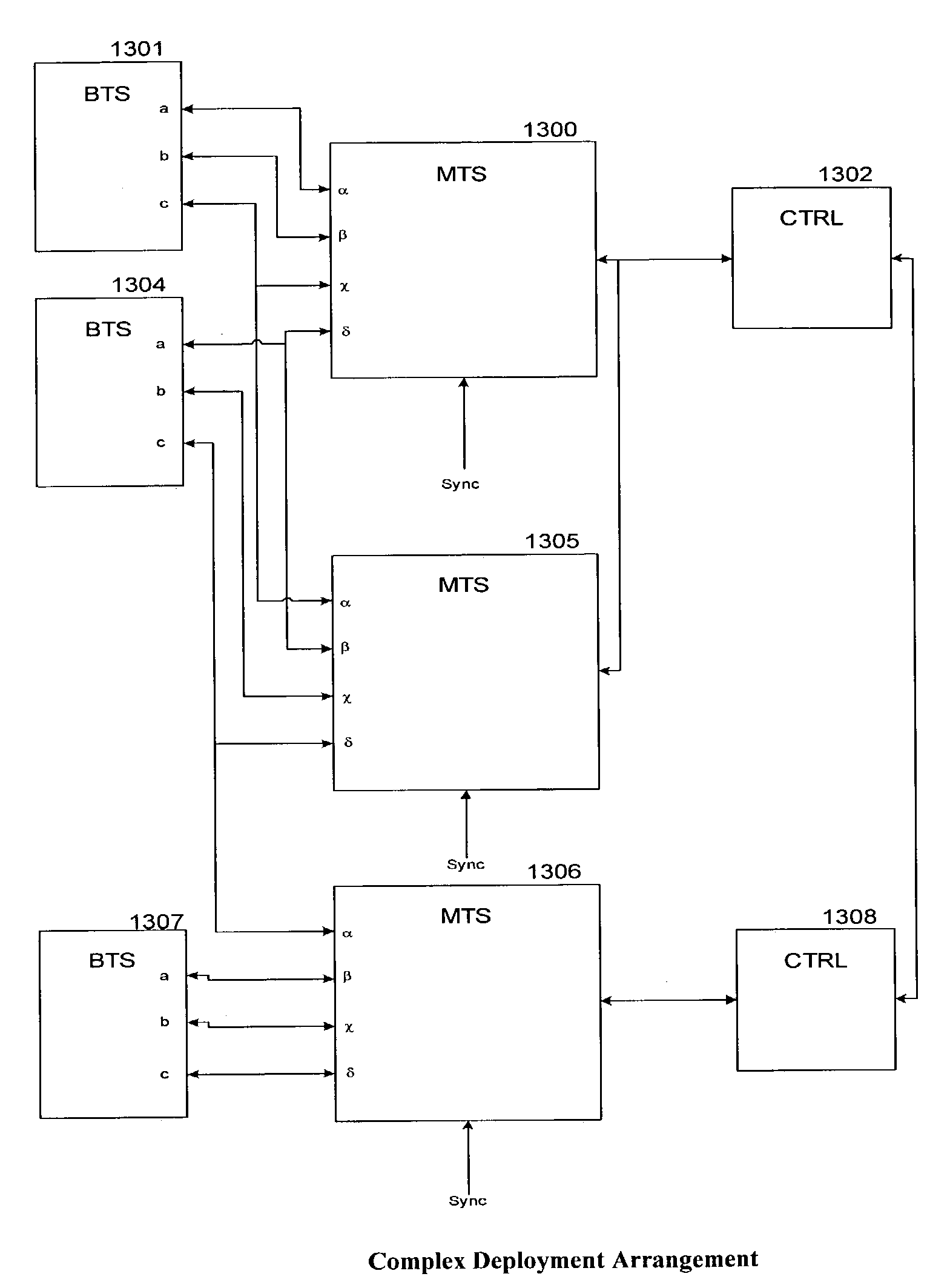
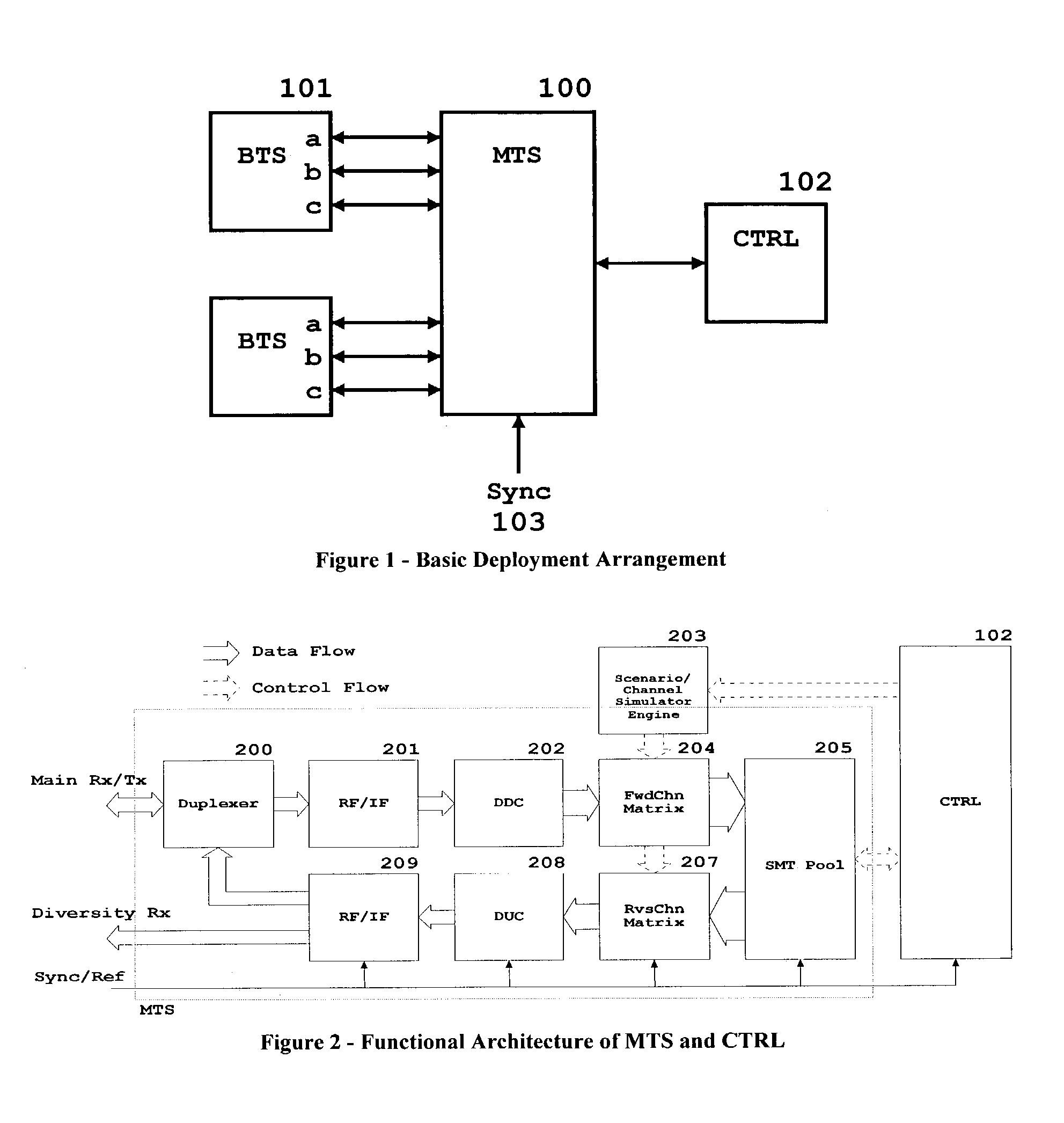
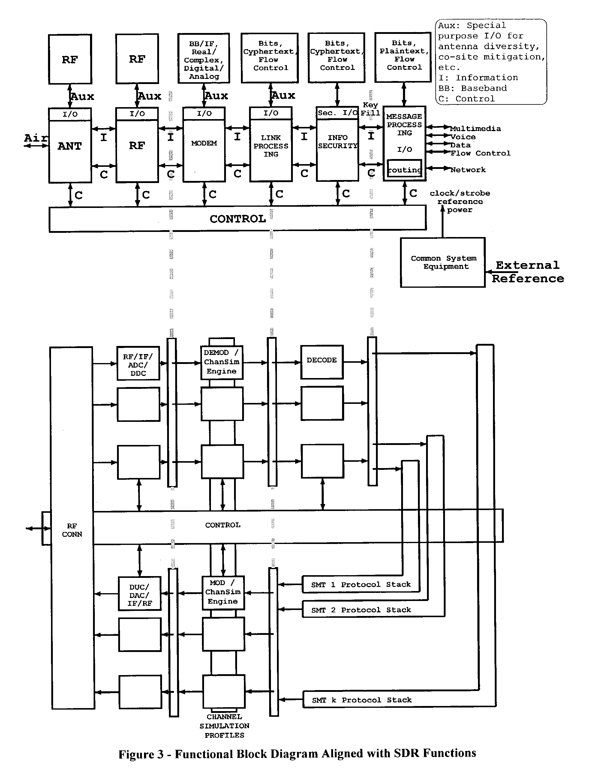
[0051]The abbreviations listed below are those commonly employed in the art (with the exceptions involving MT) and are used herein for ease of reading only. An MT is conceptually a mobile terminal. It is typically a handheld cell phone in the commercial and consumer settings, and when referenced herein as such for those settings, it is herein referred to with the adjective “discrete” (e.g. “discrete MT”) with additional adjectives (like “commercial”or “consumer” when further distinctions of a discrete MT are meant). A discrete MT is in distinction to a “simulated MT” according to the invention, which is herein abbreviated as “SMT”. The component of the invention that hosts one or more SMTs is referred to as an “MT Simulator” or herein abbreviated as “MTS”. There are varying and appropriate levels at which to view the present invention, each with its associated terminology and attendant small (nuanced instead of substantial) differences in meaning. Th...


PUM


Abstract

There is disclosed a simulator for mobile terminals within the context of a wireless network, for the purpose of testing the basestations. Channel impairments are effected during baseband processing.

Description

[0001]Priority is claimed from U.S. provisional application No. 60 / 356,728 filed Feb. 15, 2002. The entire disclosure contained therein, including the attachments thereto, is incorporated herein by this reference.1 INTRODUCTION[0002]1.1 Field of the Invention[0003]The present invention relates to testing and optimizing a collection of wireless communications network components generally, and specifically introduces a self-contained, Software-Defined Radio (SDR) platform for this purpose.[0004]1.2 Background of the Invention[0005]Wireless communications systems are composed of both network infrastructure components (e.g. basestations) and mobile terminals (MTs, typically handsets). During the product lifecycle of network and mobile terminal components, the developers and manufactures test to verify proper operation, and optimize to improve operation. During network equipment installation, commissioning, and deployment, and for ongoing network maintenance, the network operators test a...

Claims


Application Information

Patent Timeline
Patent Type & Authority Patents(United States)
IPC IPC(8): H04B17/00H04B7/005H04W24/00H04W52/04H04W52/60
CPCH04B17/0087H04W24/00H04W52/04H04B17/309H04W52/60
Inventor BEYME, STEFFENKILGOUR, CHRISSANKEY, TODD
Owner VIAVI SOLUTIONS INC
Learn More