Debugging optimized flows with breakpoints using stored breakpoint trigger indicators

a technology of breakpoint trigger indicators and flow debuggers, which is applied in the field of debugging optimized program flows, can solve the problems that the flow debugger cannot always identify a the breakpoint may not map well to a particular connection in the optimized flow, and the developer is not debugging a “true” version of the executable cod

Inactive Publication Date: 2007-10-23
GOOGLE LLC
View PDF29 Cites 24 Cited by
  • Summary
  • Abstract
  • Description
  • Claims
  • Application Information

AI Technical Summary

Benefits of technology

[0007]Through the use of mapping of flow connections and maintenance of information about connections on which breakpoints have been placed and acted upon, an optimized flow corresponding to a user defined flow may be executed for debugging. The connection information maintenance may be seen to allow for a debugger user interface that is notable for clarity and minimization of confusion of the user.

Problems solved by technology

Because of this rearrangement, a flow debugger cannot always identify a connection in the optimized flow that corresponds to a given connection in the user defined flow.
Consequently, where the user (software developer) has placed a breakpoint on the given connection between nodes in the user defined flow, this breakpoint may not map well to a particular connection in the optimized flow.
However, by doing so, the developer is not debugging a “true” (optimized) version of the executable code that will be run in a finished product.

Method used


Image

  • Debugging optimized flows with breakpoints using stored breakpoint trigger indicators
  • Debugging optimized flows with breakpoints using stored breakpoint trigger indicators
  • Debugging optimized flows with breakpoints using stored breakpoint trigger indicators

Examples


Embodiment Construction

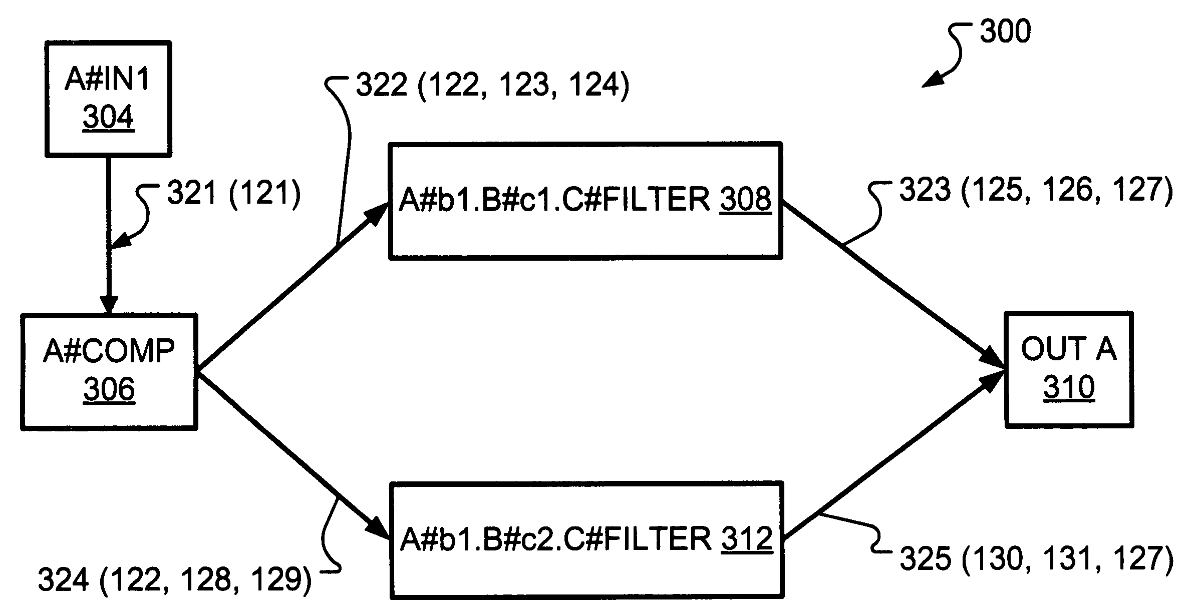
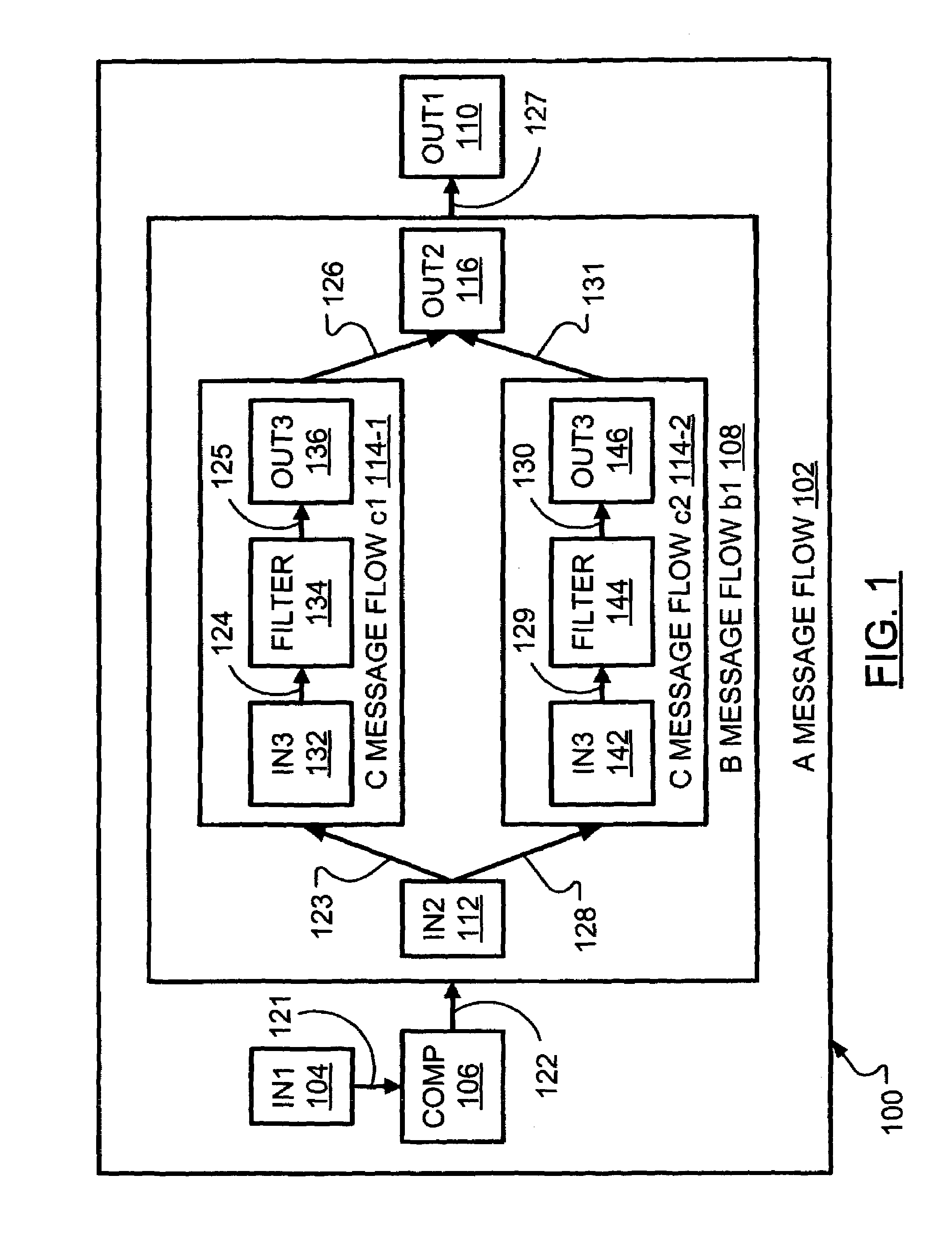
[0026]FIG. 1 illustrates an exemplary user defined flow 100. The user defined flow 100 includes an “A” nested message flow 102, which contains an instance of a “B” message flow b1108, which contains two instances of a “C” message flow, namely c1114-1 and c2114-2. By way of distinction of terminology, a connection in a user defined flow may be called a “logical” connection while a connection in an optimized flow (to be illustrated hereinafter) may be called a “physical” connection. Each logical connection between nodes in the exemplary user defined flow 100 is labeled. An input node In1104 receives a message and passes the message, over a logical connection 121, to a comp node 106. After processing the message, the comp node 106 passes the message, over a logical connection 122, to the “B” message flow b1108. After processing the message, the “B” message flow b1108 passes the message, over a logical connection 127, to an output node Out1110, which stores the message.

[0027]Within the ...


PUM


Abstract

In a development environment for message flows, a user defined flow may be processed into a more efficient optimized flow. However, debugging execution of the optimized flow may be confusing to the user where a correspondence between connections in the optimized flow and connections in the user defined flow are not direct. To mitigate this confusion, a connections mapping table is generated along with the optimized flow. The deploy document received by the runtime may include enough information to recreate the connections mapping table such that during debugging of the optimized flow, the user may follow the user defined flow. The use of a stack at the runtime allows a debugger to maintain awareness of previous pauses in execution caused by the placement of breakpoints on connections in the user defined flow while directing the runtime through execution of the optimized flow.

Description

FIELD OF THE INVENTION[0001]The present invention relates to debugging program flows and, in particular, debugging optimized program flows.BACKGROUND OF THE INVENTION[0002]It has become commonplace, of late, for software developers to employ programming tools when developing program code. Such tools may include environments for efficiently writing (an editor), compiling (a compiler), executing (a runtime) and debugging the execution of (a debugger) program code. It is well accepted that program may be referred to in terms of a program “flow” that is representative of components of a whole that is a program, or a part thereof. The components are typically lines of code set apart from other lines of code based on the purposed served. The components may be seen as “nodes” in a flow map, which may also be called a flow graph or flow chart. Between the nodes may be “connections” that indicate the nodes that follow other nodes in the flow.[0003]Debugging code often requires that breakpoin...

Claims


Application Information

Patent Timeline
Patent Type & Authority Patents(United States)
IPC IPC(8): G06F9/44G06F9/45G06F11/36
CPCG06F11/3628
Inventor TAN, SHU XIAMAMAS, EVANGELOSO'FARRELL, WILLIAM GERALDSEELEMAN, II, ALEXANDERMAK, VIVIAN
Owner GOOGLE LLC
Why Eureka
Try Eureka