Single component automotive bumper and lower frame rail

a technology of which is applied in the direction of bumpers, vehicle components, understructures, etc., can solve the problems that the bumper and frame structure is not particularly well suited to modem automotive manufacture, and achieve the effect of enhancing crash performance, uniform cross-sectional configuration, and reducing manufacturing costs of the bumper and lower frame rail

Inactive Publication Date: 2007-10-30
VARI FORM +1
View PDF12 Cites 7 Cited by
  • Summary
  • Abstract
  • Description
  • Claims
  • Application Information

AI Technical Summary

Benefits of technology

[0008]It is a feature of this invention that the bumper structure can be formed through hydroforming processes to enhance manufacturing efficiencies.
[0009]It is an advantage of this invention that the cross-sectional configuration of the bumper beam can be uniformly manufactured along the entire length of the bumper beam and extending through the lower frame rails.
[0011]It is still another feature of this invention that the bumper beam can be formed with crash triggers to direct the deformation of the bumper and lower frame rail in a manner to enhance crash performance.
[0012]It is a further advantage of this invention that the manufacturing cost of a bumper and lower frame rail can be lowered without sacrificing crash performance characteristics.
[0013]It is another object of this invention to provide a single component bumper beam and lower frame rail structure that is durable in construction, inexpensive of manufacture, facile in assemblage, and simple and effective in use.
[0014]These and other objects, features and advantages are accomplished according to the instant invention by providing a single component bumper beam and lower frame rail structure, which can be formed through a hydroforming process to create a uniform “B-shaped” cross-sectional configuration with internal crash triggers to enhance crash performance. The mounting legs of the integral bumper structure are formed with a reduced cross-section at the terminal ends thereof to facilitate insertion into lower frame rails formed from a pair of horizontally disposed tubes. The terminal end portions of the mounting legs are formed with a longitudinally extending slot to receive a central co-joined wall member formed through the welding of the two vertically oriented tubular members in the lower frame rails. The single component bumper and longitudinally extending mounting leg structure can be formed by welding together two vertically oriented tubes.

Problems solved by technology

Such bumper and frame structure is not particularly well suited to modem automotive manufacture.

Method used


Image

  • Single component automotive bumper and lower frame rail
  • Single component automotive bumper and lower frame rail
  • Single component automotive bumper and lower frame rail

Examples


Embodiment Construction

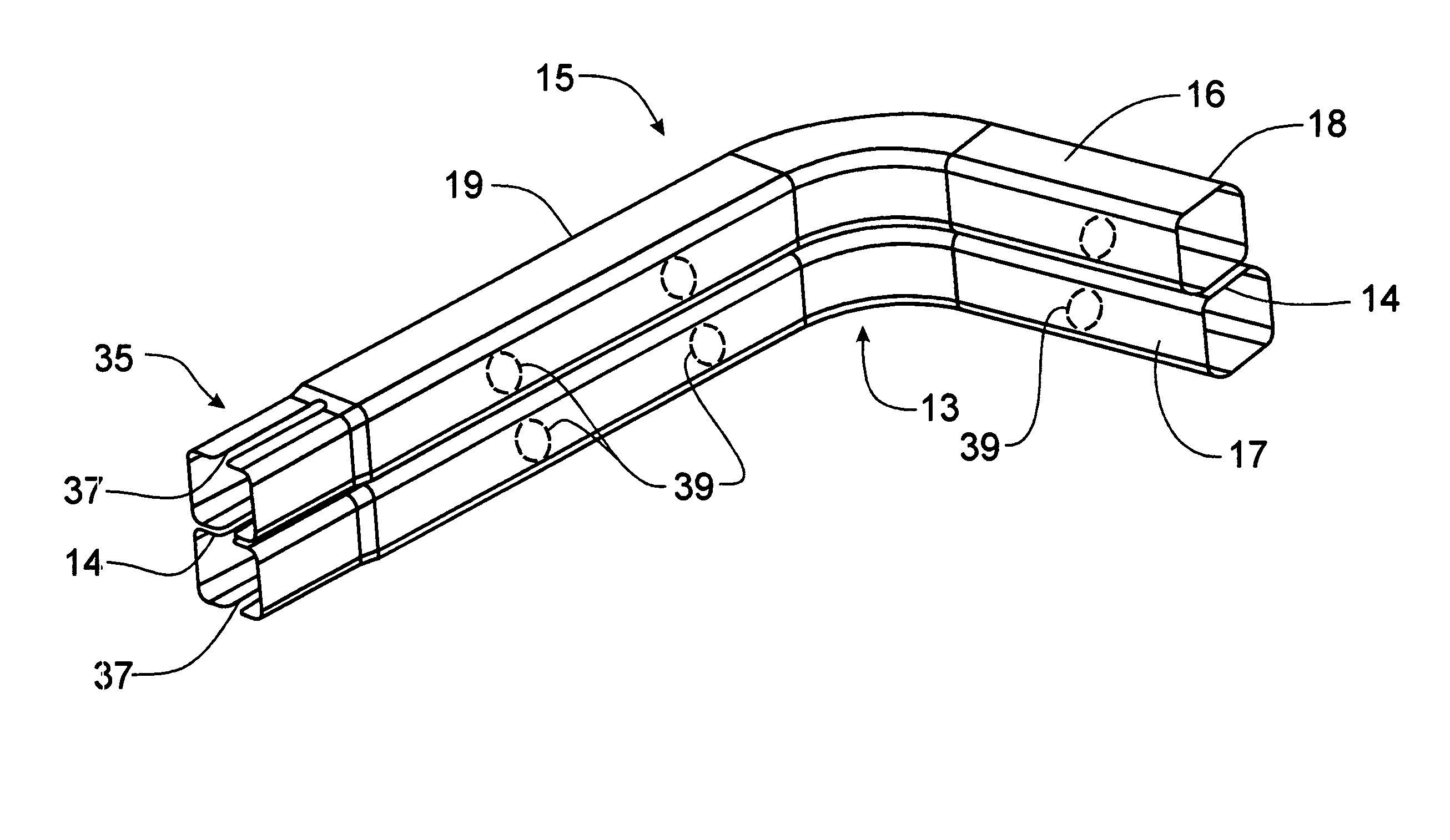
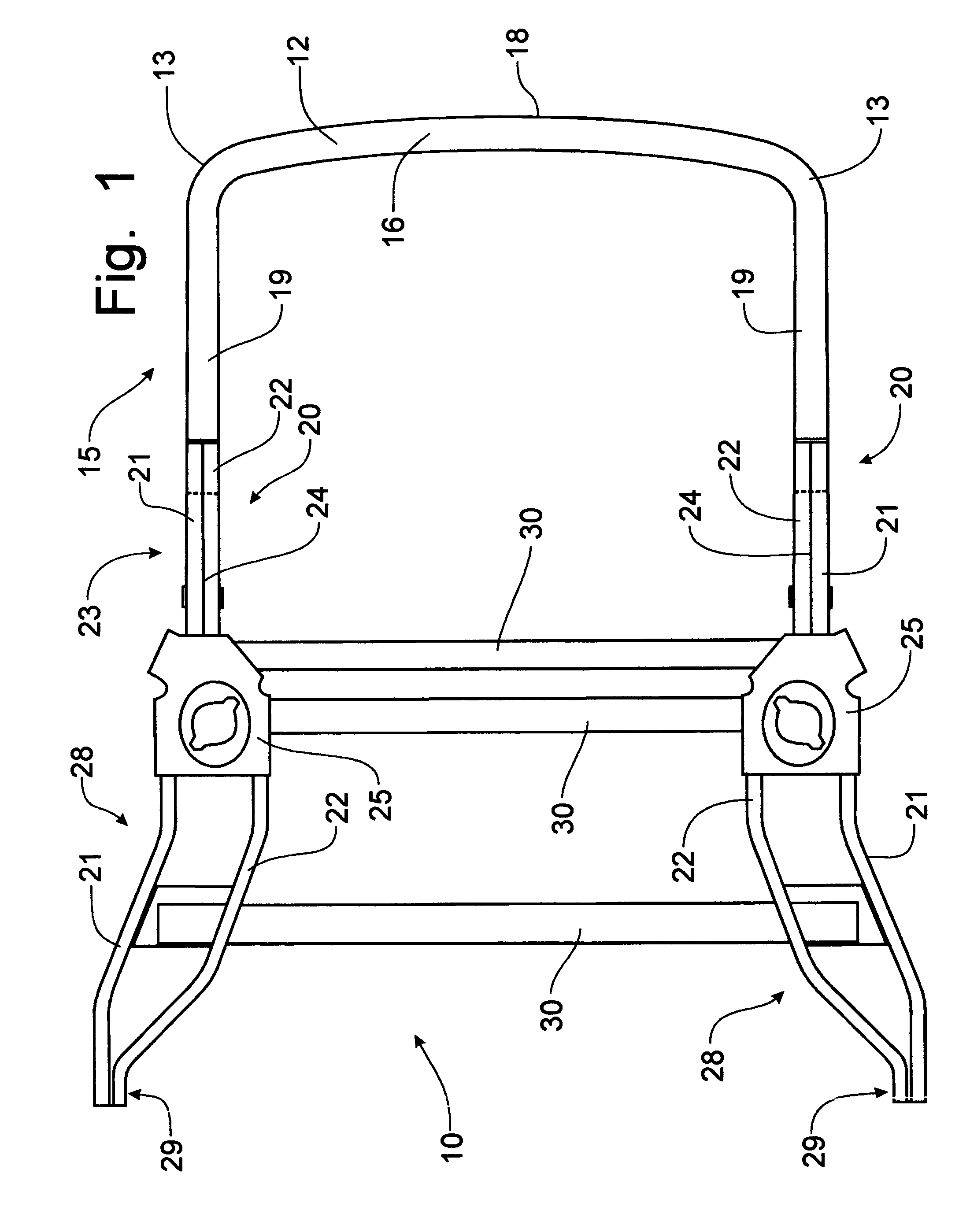
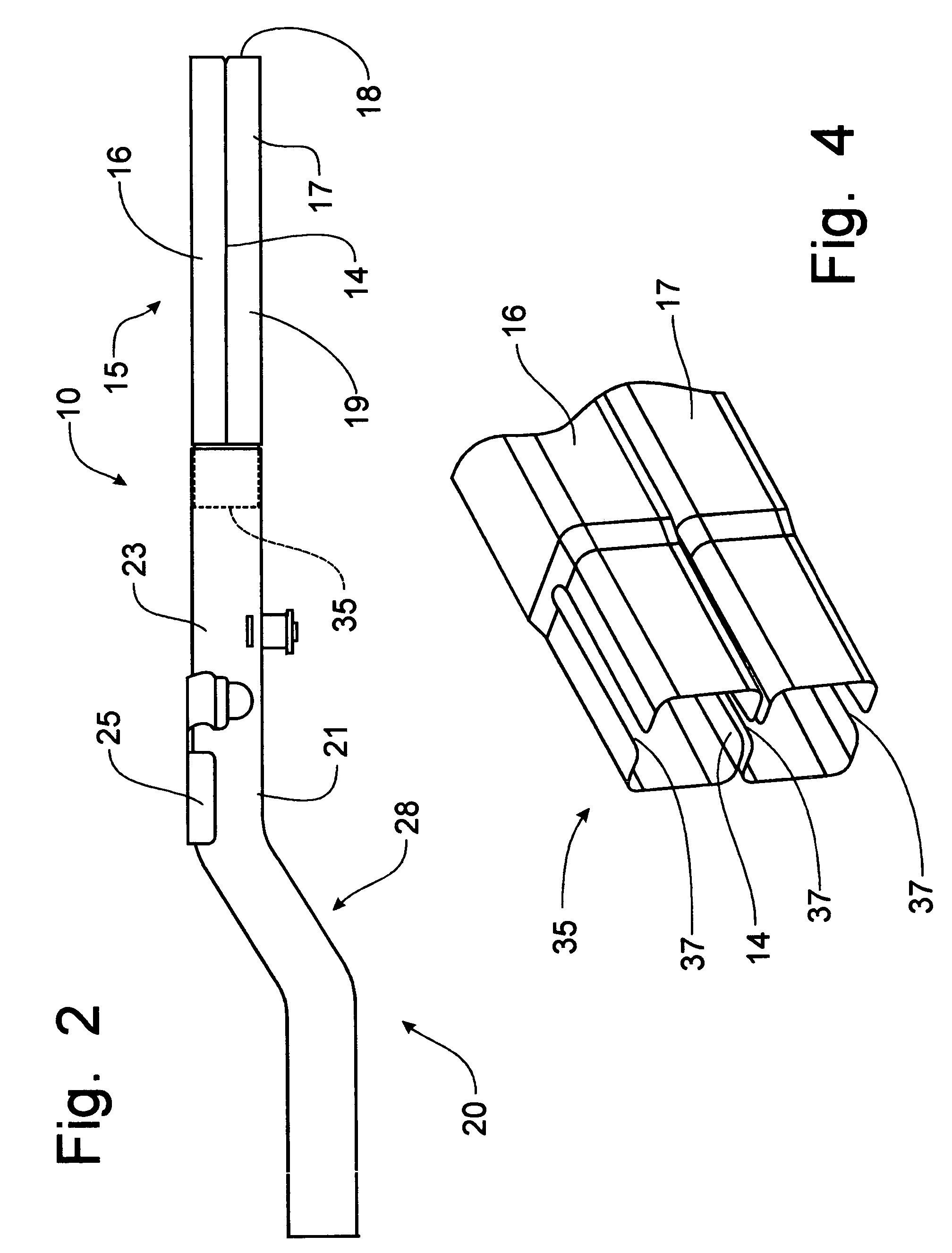
[0023]Referring to FIGS. 1 and 2, a bumper and lower frame rail, including the midrails having a shock tower support mounted thereon, forming the rear end of an automobile frame and incorporating the principles of the instant invention, can best be seen. The frame 10 of the automobile is preferably formed from hydroformed tubular members. Such tubular members can be spot-welded and / or MIG-welded to form an integral frame assembly for the rear end of a vehicle.

[0024]Hydroforming is a process by which a standard tubular stock member is placed into a form shaped to correspond to the particular member to be formed and to correspond to the particular section required for the frame design. A liquid is then introduced into the interior of the tubular stock and pressurized until the tubular stock expands to assume the shape defined by the configured form The expanded and re-shaped tubular stock now has a substantially different shape. By forming cutouts and other access openings into the re...


PUM


Abstract

A single component bumper beam and lower frame midrail structure, is formed through a hydroforming process to create a uniform “B-shaped” cross-sectional configuration with internal crash triggers to enhance crash performance. The mounting legs of the integral bumper structure are formed with a reduced cross-section at the terminal ends thereof to facilitate insertion into lower frame midrails formed from a pair of horizontally disposed tubes. The terminal end portions of the mounting legs are formed with a longitudinally extending slot to receive a central co-joined wall member formed through the welding of the two vertically oriented tubular members in the lower frame midrails. The single component bumper and longitudinally extending mounting leg structure can be formed by welding together two vertically oriented tubes.

Description

FIELD OF THE INVENTION[0001]This invention relates to a bumper for an automotive vehicle and, more particularly, to a rear bumper and lower frame rail formed from a single hydroformed component for attachment to the lower frame midrails.BACKGROUND OF THE INVENTION[0002]Bumpers are mounted at the forward and rearward extremities of a vehicle to protect the chassis of the vehicle from minor impacts. The bumper is mounted to the lower frame rails of the vehicle chassis for support thereof and functions to withstand minor impacts by collapsing to absorb the energy encountered through the impact.[0003]The structure of a bumper can be formed in a “B-shaped” configuration with a front face flange and upper and lower cells. This B-shaped structural configuration can be seen in U.S. Pat. No. 6,510,771, issued to Peter Sturrus, et al on Jan. 28, 2003. The Sturrus patent discloses a bumper having a transversely extending member shaped in the “B” configuration with the bumper having upper and l...

Claims


Application Information

Patent Timeline
Patent Type & Authority Patents(United States)
IPC IPC(8): B60R19/04
CPCB62D21/152B60R19/24
Inventor CALISKAN, ARIGERICKE, DEAN
Owner VARI FORM
Why Eureka
Try Eureka