Optical connector assembly, connector holder, and optical connector

a technology of optical connectors and connector holder, which is applied in the direction of optics, instruments, optical light guides, etc., can solve the problems of limiting the degree of freedom of design of optical connection paths and circuit substrates, and the inability to miniaturize substrates, so as to achieve easy positioning of optical connectors with respect to optical elements, the degree of freedom of design of installation position is increased, and the effect of ensuring stability

Active Publication Date: 2007-10-30
FUJIKURA LTD
View PDF36 Cites 38 Cited by
  • Summary
  • Abstract
  • Description
  • Claims
  • Application Information

AI Technical Summary

Benefits of technology

[0006]In consideration of the problems described above, an object of the invention is to provide an optical connector assembly, a connector holder, and an optical connector in which a structure for installing the optical connector on a substrate having optical elements mounted thereon can be miniaturized, the installation of the optical connector onto the substrate is easy, the degree of freedom of the design of the installation position is increased, and furthermore, the positioning of the optical connector with respect to the optical elements is easy and the precision of the positioning can be stably maintained over a long term.

Problems solved by technology

However, accompanying the recent strengthening of requirements for optoelectric hybrid circuits and optoelectric mixed-signal substrates, because each type of optical transceiver having such a configuration has restrictions with respect to the installation position of the optical connector, problems are encountered in that the degree of freedom of the design of the optical connection paths and circuit substrates has become restricted, and furthermore, the substrate cannot be miniaturized.

Method used


Image

  • Optical connector assembly, connector holder, and optical connector
  • Optical connector assembly, connector holder, and optical connector
  • Optical connector assembly, connector holder, and optical connector

Examples


Embodiment Construction

[0053]Exemplary embodiments of the invention will now be explained with reference to the drawings. The described exemplary embodiments are intended to assist the understanding of the invention, and are not intended to limit the scope of the invention in any way. For example, the elements of these embodiments can be appropriately combined together.

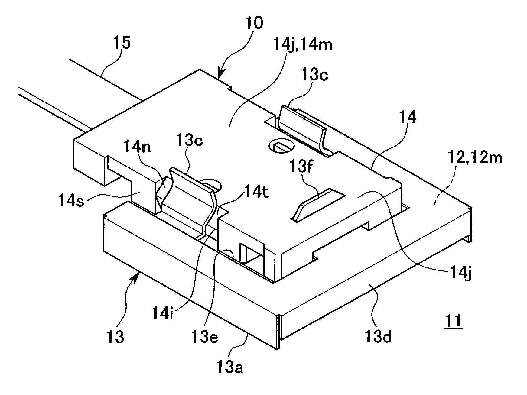
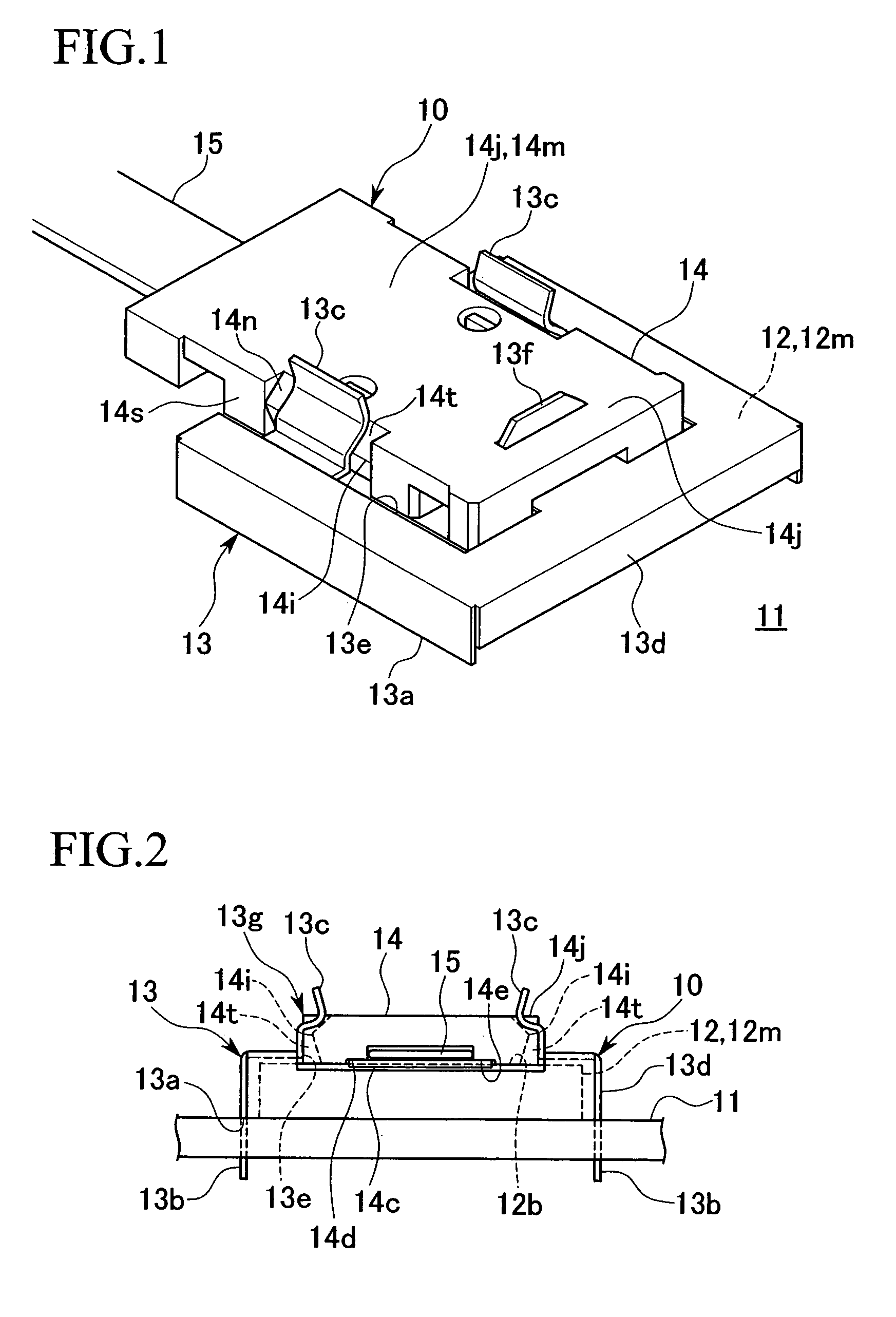
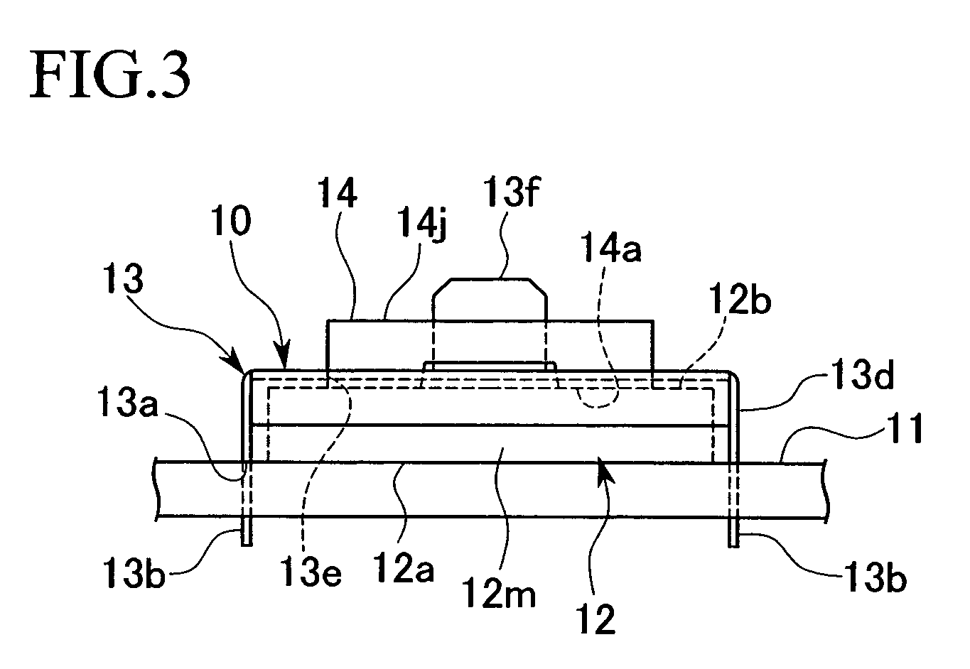
[0054]FIG. 1 to FIG. 4B are drawings showing the optical connector assembly (denoted by reference numeral 10, and may also be referred to as the optical connector fastening structure). FIG. 1 is a general perspective view, FIG. 2 is a side view (a side view seen from the side in which the optical fiber 15 extends), FIG. 3 is a side view from the side opposite to that shown in FIG. 2, FIG. 4A is a plan view, and FIG. 4B is a front cross-sectional view.

[0055]In FIG. 1 to FIG. 4B, reference numeral 11 denotes a circuit substrate, 12 denotes a photoelectric conversion module, 13 denotes a connector holder, 14 denotes an optical connector, and 1...


PUM


Abstract

An optical connector assembly includes a substrate including a connection surface and an optical element, an optical connector on a distal end of an optical fiber, and a positioning mechanism, that positions the optical fiber with respect to the optical element to provide an optical connection therebetween, the positioning mechanism including a positioning projection on one of the optical connector and the substrate and a corresponding positioning hole on the other of the optical connector and the substrate.

Description

CROSS-REFERENCE TO RELATED APPLICATION[0001]This is a Continuation Application of International Application No. PCT / JP2004 / 006120, filed Apr. 28, 2004, which is based upon and claims the benefit of priority from Japanese Patent Application No. 2003-125350, filed Apr. 30, 2003. The contents of the aforementioned applications are incorporated herein in their entirety by reference.BACKGROUND OF THE INVENTION[0002]1. Field of the Invention[0003]The invention relates to an optical connector assembly, a connector holder, and an optical connector having a fastening structure in which an optical connector provided at the distal end of an optical fiber can be mounted on an optical output-input terminal provided on a substrate and positioned at a position that enables an optical connection to the optical input-output terminal.[0004]2. Description of Related Art[0005]Presently, optical transceivers used in optical LAN systems or the like generally employ a configuration in which the optical ax...

Claims


Application Information

Patent Timeline
Patent Type & Authority Patents(United States)
IPC IPC(8): G02B6/36G02B6/42
CPCG02B6/4214G02B6/4292G02B6/4249
Inventor FUJIWARA, KUNIHIKOISHIKAWA, TAKAAKI
Owner FUJIKURA LTD
Why Eureka
Try Eureka