Brush block for transmitting currents

a brush block and current technology, applied in current collectors, dynamo-electric machines, electrical apparatus, etc., can solve the problem of insufficient contact and achieve the effect of reducing contact resistance, reducing wear, and extending contact area

Active Publication Date: 2007-10-30
WALTER KRAUS
View PDF11 Cites 8 Cited by
  • Summary
  • Abstract
  • Description
  • Claims
  • Application Information

AI Technical Summary

Benefits of technology

[0009]The device for transmitting currents comprises essentially at least one brush block, which is connected with a plurality of multiwire sliding elements (MWSE), wherein these MWSE can be brought tangentially into contact with a slip ring. The use of such a plurality of MWSE has the advantage that the current to be transmitted is distributed among a plurality of contacts connected in parallel. As a result, the current power to be transmitted per MWSE is greatly reduced, as a consequence of which wear due to heating is greatly reduced and it is, above all, possible to also transmit power currents with current intensities of 40 A or higher. Furthermore, sufficient contact is still present even in case of wear-related loss of contact of individual MWSE to guarantee sufficient transmission of the current. As a result, the service life of the device is prolonged and the risk of failure is reduced.
[0024]In another embodiment of the present invention, the slip ring comprises two or more segments, which are insulated from one another and which are supplied with different currents via a plurality of differently poled brush blocks. It is achieved as a result that a plurality of currents can be transmitted on only one slip ring circumference in a space-saving manner in order to bring about, for example, pole reversals at regular intervals.

Problems solved by technology

Furthermore, sufficient contact is still present even in case of wear-related loss of contact of individual MWSE to guarantee sufficient transmission of the current.

Method used


Image

  • Brush block for transmitting currents
  • Brush block for transmitting currents
  • Brush block for transmitting currents

Examples


Embodiment Construction

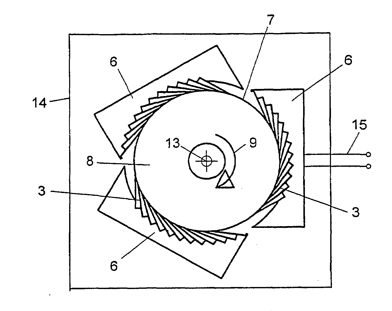
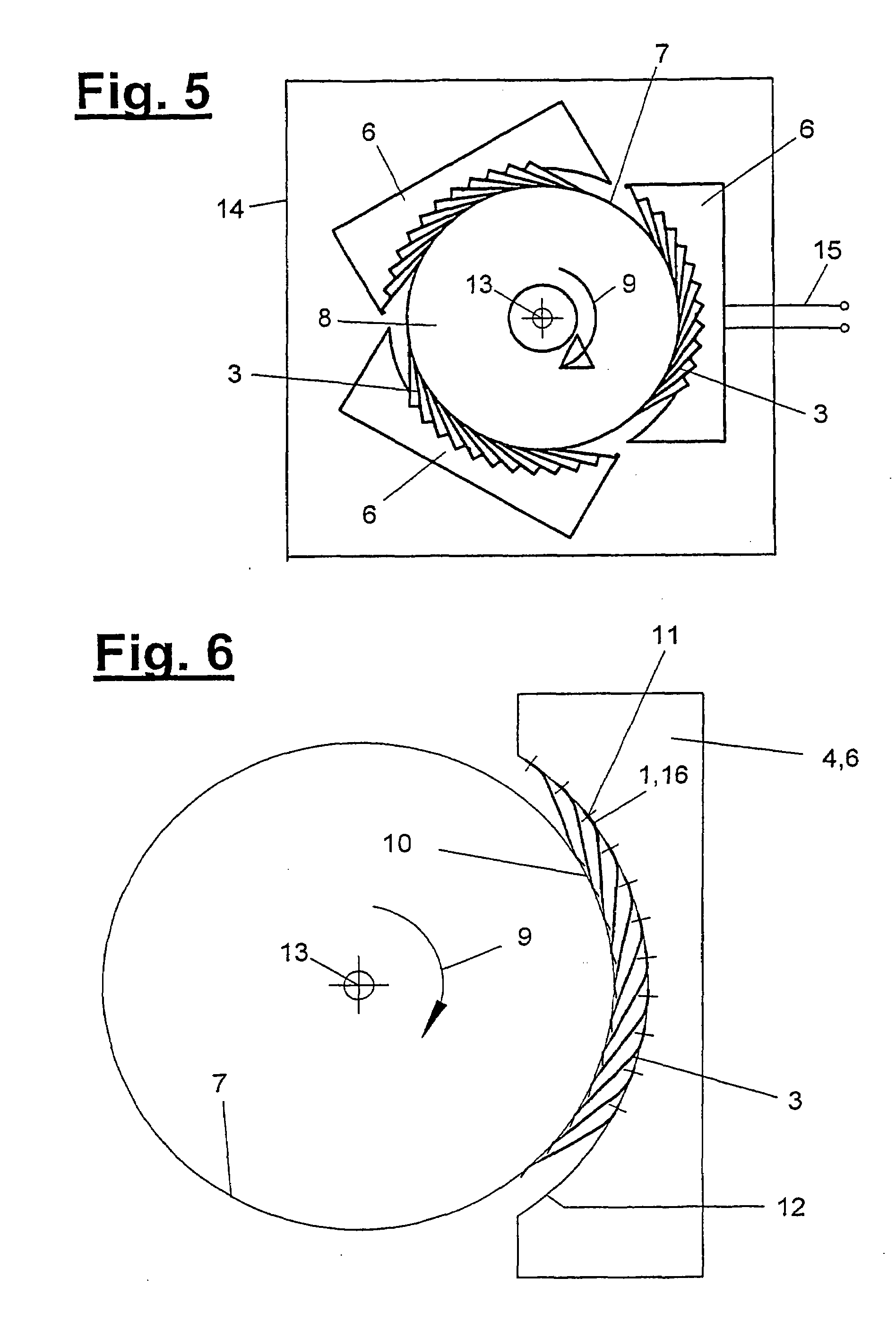
[0034]Referring to the drawings in particular, in a preferred embodiment of the present invention, the brush block generally designated 6 is used to transmit power currents to a slip ring 7, which is mounted on the circumferential side of a cylindrical carrier 8 rotating about the axis 13. The kinematic arrangement may also be reversed. The brush block 6, which is present as one brush block or as a plurality of brush blocks, and the one or more slip rings 7 arranged in parallel form a current transmission unit 14. FIG. 5 schematically shows a current transmission unit 14 with terminals 15 for power current, which are connected to the brush blocks 6. The slip ring or slip rings 7 has / have corresponding current connections.

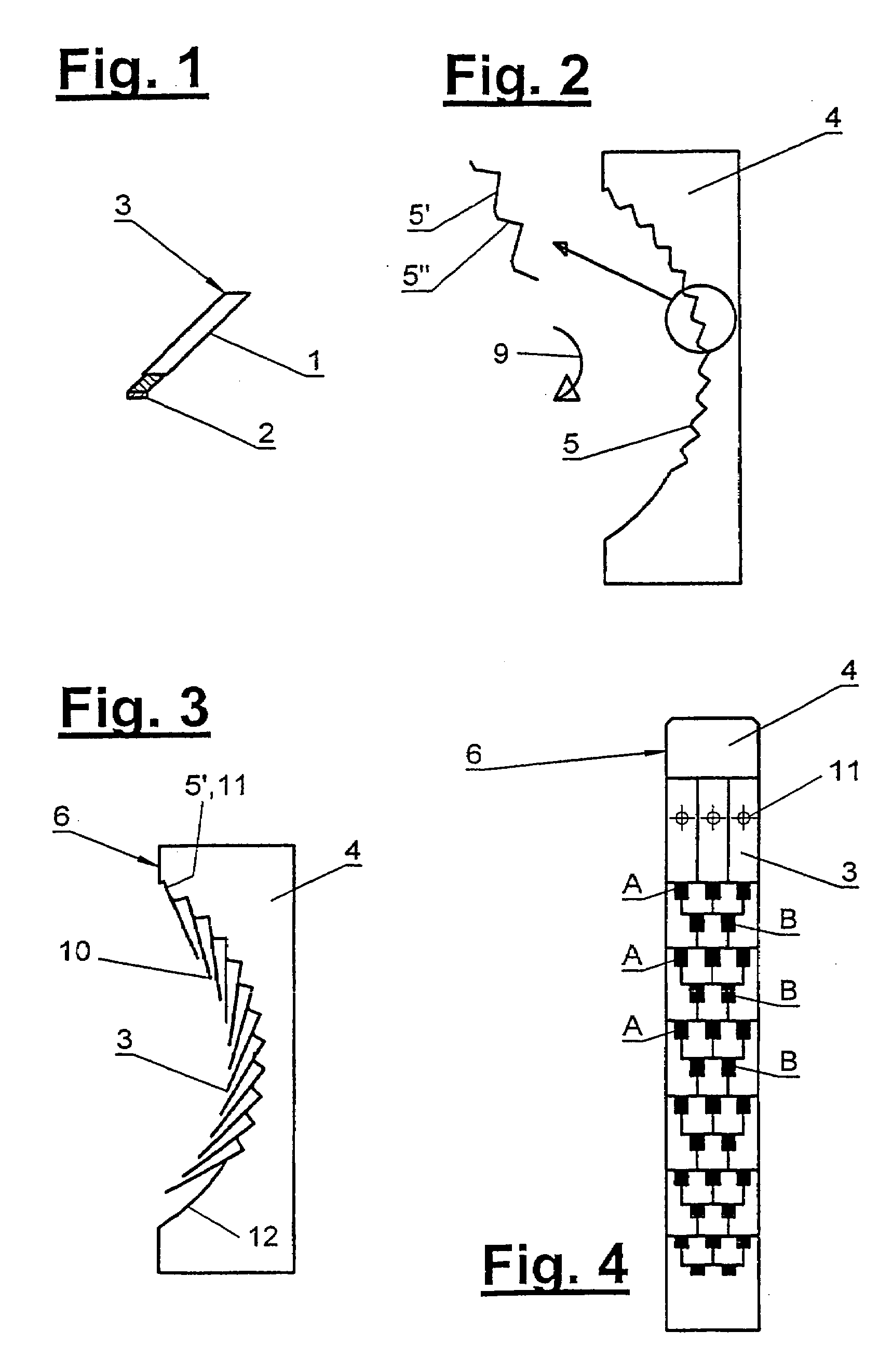
[0035]The brush block 6 comprises a plurality of multiwire sliding elements 3 (hereinafter called MWSE), which are connected electrically in parallel and are arranged and fastened in a uniformly distributed pattern at an MWSE carrier 4 in the direction of sliding 9....


PUM


Abstract

A brush block is provided for transmitting currents to a slip ring using at least one multi-wire slip element with a plurality of parallel connected multi-wire slip elements that are distributed one behind the other in the direction of slip following an imaginary curve. The brush block has a multi-wire slip element support with a curved inner wall on which the multi-wire slip elements are disposed in layers that overlap in scale-like fashion.

Description

CROSS REFERENCE TO RELATED APPLICATIONS[0001]This application is a United States National Phase application of International Application PCT / EP2004 / 008838 filed Aug. 6, 2004 and claims the benefit of priority under 35 U.S.C. § 119 of German Patent Application DE 203 12 458.8 filed Aug. 13, 2003, the entire contents of which are incorporated herein by reference.FIELD OF THE INVENTION[0002]The present invention pertains to a brush block for transmitting currentsBACKGROUND OF THE INVENTION[0003]Devices for transmitting currents to a slip ring by means of a maximum of two sliding contacts have been known so far, which are suitable for transmitting signal currents with a current intensity in the mA range. These devices cannot transmit higher current intensities.[0004]Since only a maximum of two sliding contacts are used to transmit the current, these devices imply a risk of failure, because the functionality of the entire device depends on a maximum of two individual elements subject to ...

Claims


Application Information

Patent Timeline
Patent Type & Authority Patents(United States)
IPC IPC(8): H01R39/00H01R39/24H01R39/38
CPCH01R39/24H01R39/38
Inventor BÜTLER, OLAF
Owner WALTER KRAUS
Why Eureka
Try Eureka