Device for measuring and correcting the luminance of a display

a technology for adjusting devices and displays, applied in the direction of identification means, instruments, light sources, etc., can solve the problems of not being able to measure, not being able to be corrected, affecting the luminance of an image displayed on the display panel, etc., and achieve the effect of largely correcting effects

Active Publication Date: 2007-10-30
EIZO
View PDF4 Cites 8 Cited by
  • Summary
  • Abstract
  • Description
  • Claims
  • Application Information

AI Technical Summary

Benefits of technology

[0005]An object of the present invention is to provide a device for use with a display panel, and particularly for use with a flat screen display panel, which makes it possible to measure and to largely correct effects due to influences such as aging and / or temperature of the display panel, for example, which interfere with the luminance of the display panel.

Problems solved by technology

The drawback is that such a backlight control measures and regulates only the luminance of the backlight, while influences affecting the luminance of an image displayed on the display panel are not measured and, therefore, can not be corrected.
For example, it is not possible to measure and to correspondingly correct effects that interfere with the luminance of the image due to aging of the glass, the LCD fluid, or the diffuser and / or polarization foils of the display panel.
The drawback is that, for example, the temperature influences within the flat screen and outside the flat screen differ, so that the luminance can only be detected imprecisely.

Method used


Image

  • Device for measuring and correcting the luminance of a display
  • Device for measuring and correcting the luminance of a display
  • Device for measuring and correcting the luminance of a display

Examples


Embodiment Construction

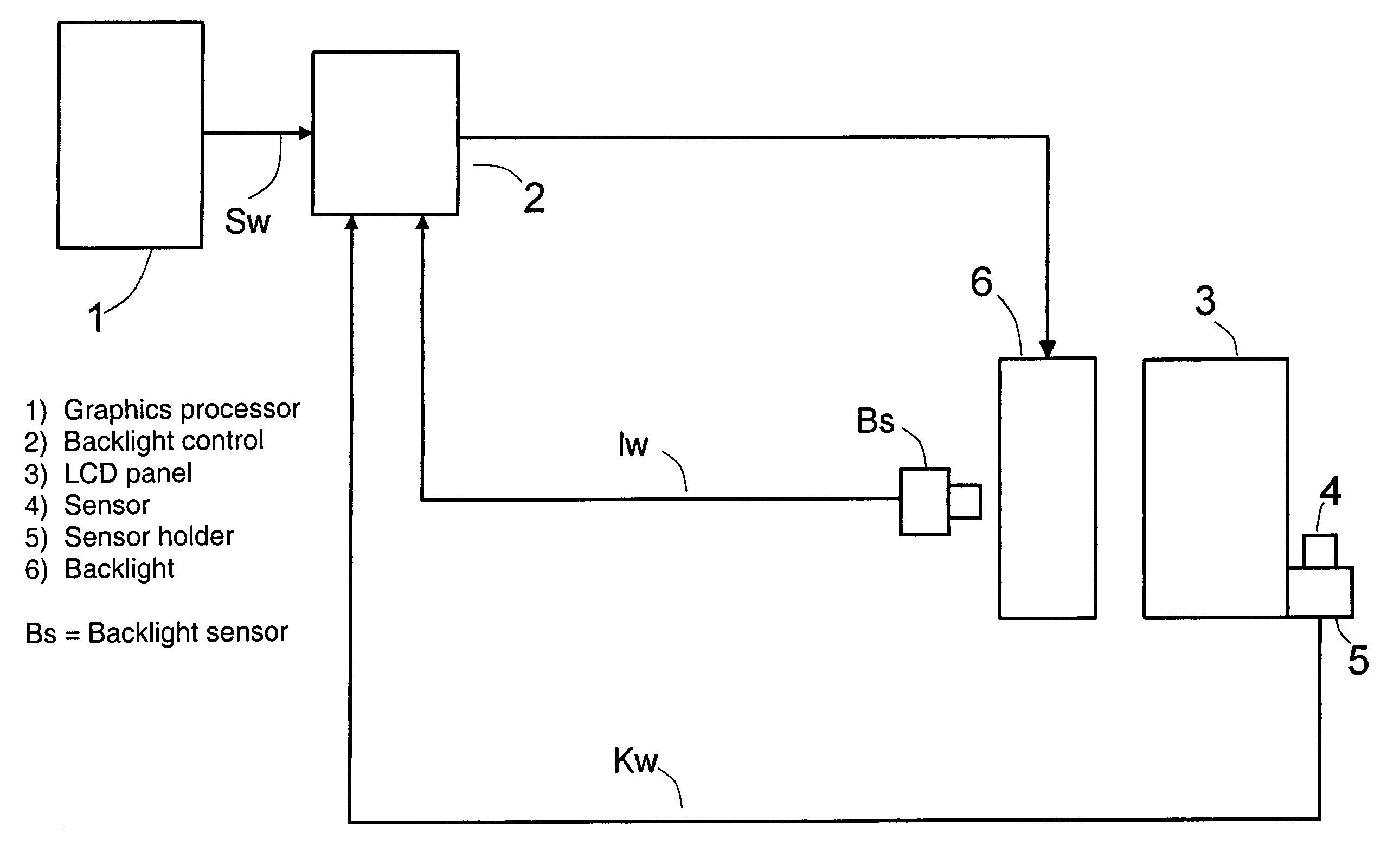
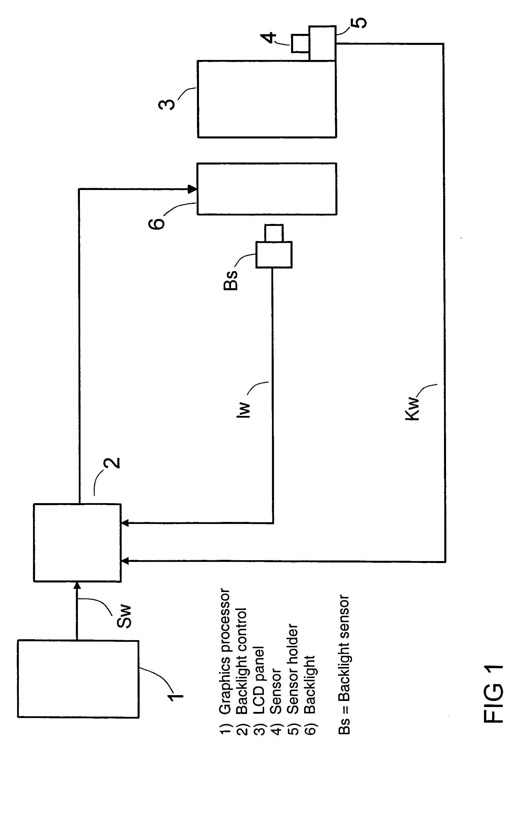
[0022]In FIG. 1, 1 identifies a graphics processor, which can be supplied with digitized image information (not depicted) for display on an LCD panel 3 of a flat screen display. The graphics processor 1 transmits a selectable setpoint value Sw to the backlight control 2. The backlight control 2 adjusts the luminance of the LCD panel 3 substantially constantly to a desired luminance that corresponds to the setpoint value Sw. In a factory setting, the setpoint value Sw is defined such that the luminance of an image that can be displayed on the LCD panel 3 imparts an optimal impression of the image. To adjust the luminance, a backlight sensor Bs is provided to measure the light from a backlight 6, which illuminates the LCD panel 3 from the rears and the light intensity of which effects a corresponding luminance on the LCD panel 3. The backlight sensor Bs feeds an actual value Iw corresponding to this luminance of the backlight 6 to the backlight control 2, which adjusts this actual val...


PUM

PropertyMeasurementUnit
light intensityaaaaaaaaaa
luminanceaaaaaaaaaa
areaaaaaaaaaaa

Abstract

A device for measuring and correcting the luminance of a flat screen display, which can be illuminated from the rear by the light of a backlight, having a backlight control, which adjusts a luminance measured by a sensor to a selectable setpoint value representing the intensity of the light of the backlight. The sensor is arranged in an area of the flat screen display device that is not visible to a viewer, and a swivel is provided to swivel the sensor out, essentially parallel to the display panel, from a standby position to a position for measuring the luminance of a test image that can be displayed on the display panel during a calibration phase. As a result, effects due to aging and/or temperature of the display panel and interfering with the luminance of the display panel are detected and can be largely corrected.

Description

[0001]The following disclosure is based on German Patent Application No. 103 39 503.2, filed on Aug. 27, 2003, which is incorporated into this application by reference in its entirety.FIELD AND BACKGROUND OF THE INVENTION[0002]The present invention relates to a device for use with a display panel, and particularly for use with a flat screen display panel, which can be illuminated from the rear by means of a backlight, having a backlight control to adjust a luminance measured by a sensor to a selectable setpoint value, which represents the intensity of the backlight.[0003]To control the luminance of a backlight for a liquid crystal display (“LCD”) panel and flat screen LCD displays, a backlight control is usually provided. This backlight control adjusts the luminance of the backlight illuminating the display panel from the rear and measured by a sensor to an essentially constant setpoint value. The drawback is that such a backlight control measures and regulates only the luminance of...

Claims


Application Information

Patent Timeline
Patent Type & Authority Patents(United States)
IPC IPC(8): G09G3/10G02F1/13357G09F9/00G09F9/35G09G3/34G09G3/36
CPCG09G3/3406G02F1/1336G02F2201/58G09G2360/145G09G2320/0626G09G2320/0693G09G2320/041
Inventor EDELBROCK, RALF
Owner EIZO
Why Eureka
Try Eureka