Plasma potential measuring method and apparatus, and plasma potential measuring probe

a technology of plasma potential and measuring probe, which is applied in the field of plasma potential measuring method and apparatus, can solve the problems of difficult accurate measurement and deterioration of repeatability in measurement, and achieve the effect of reducing error factor and good repeatability in measuremen

Inactive Publication Date: 2007-10-30
HITACHI CABLE +1
View PDF9 Cites 12 Cited by
  • Summary
  • Abstract
  • Description
  • Claims
  • Application Information

AI Technical Summary

Benefits of technology

[0009]It is an object of the invention to provide a plasma potential measuring method that has a reduced error factor and a good repeatability in measurement.
[0010]It is a further object of the invention to provide a plasma potential measuring apparatus that has a reduced error factor and a good repeatability in measurement.
[0011]It is a further object of the invention to provide a plasma potential measuring probe that has a reduced error factor and a good repeatability in measurement.

Problems solved by technology

However, the emissive probe method has some problems Namely, due to some error factors thereof, it is difficult to conduct the accurate measurement.
Further, the filament 101 significantly wastes with time, and therefore the repeatability in measurement will deteriorate.

Method used


Image

  • Plasma potential measuring method and apparatus, and plasma potential measuring probe
  • Plasma potential measuring method and apparatus, and plasma potential measuring probe
  • Plasma potential measuring method and apparatus, and plasma potential measuring probe

Examples


Embodiment Construction

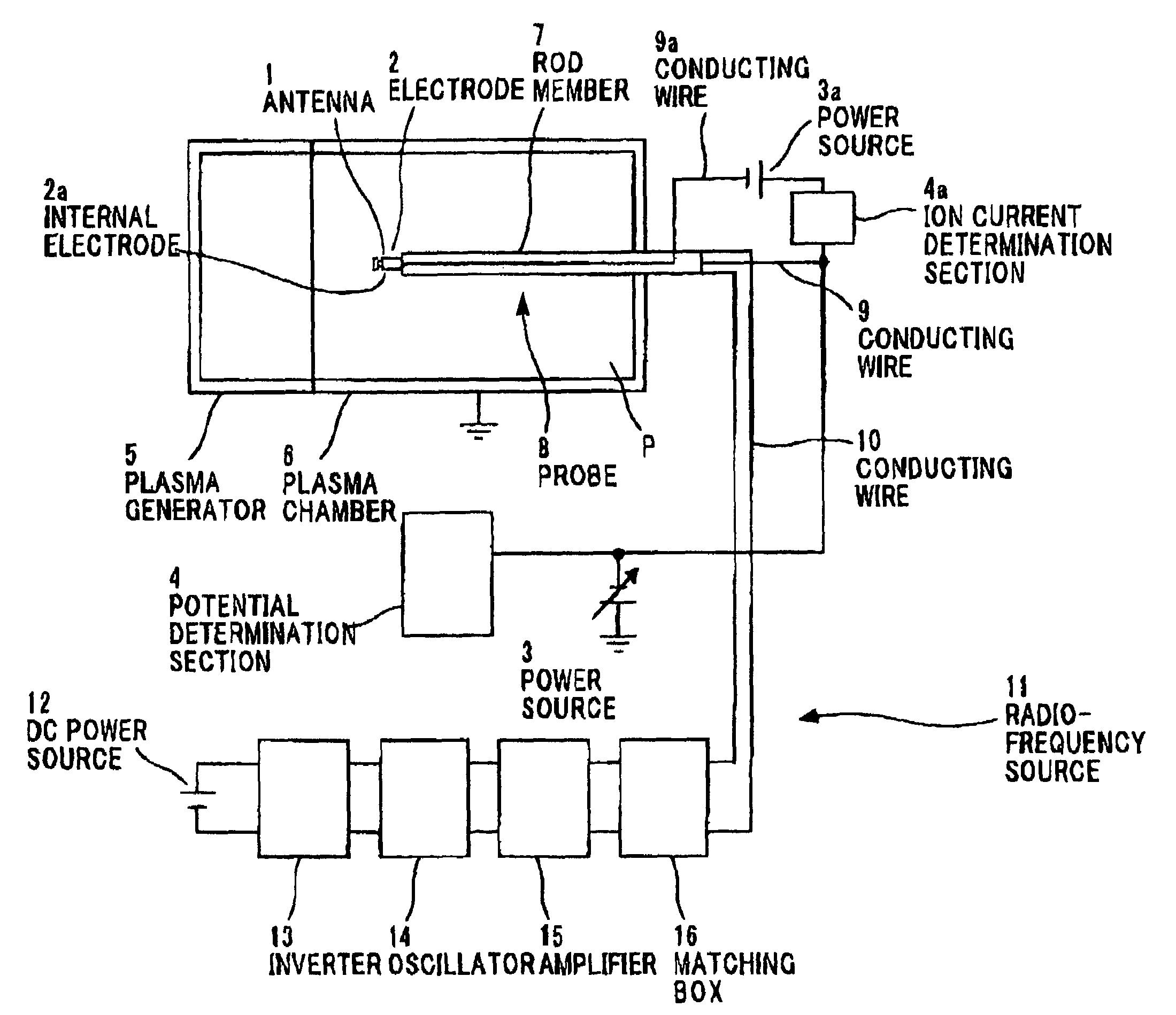
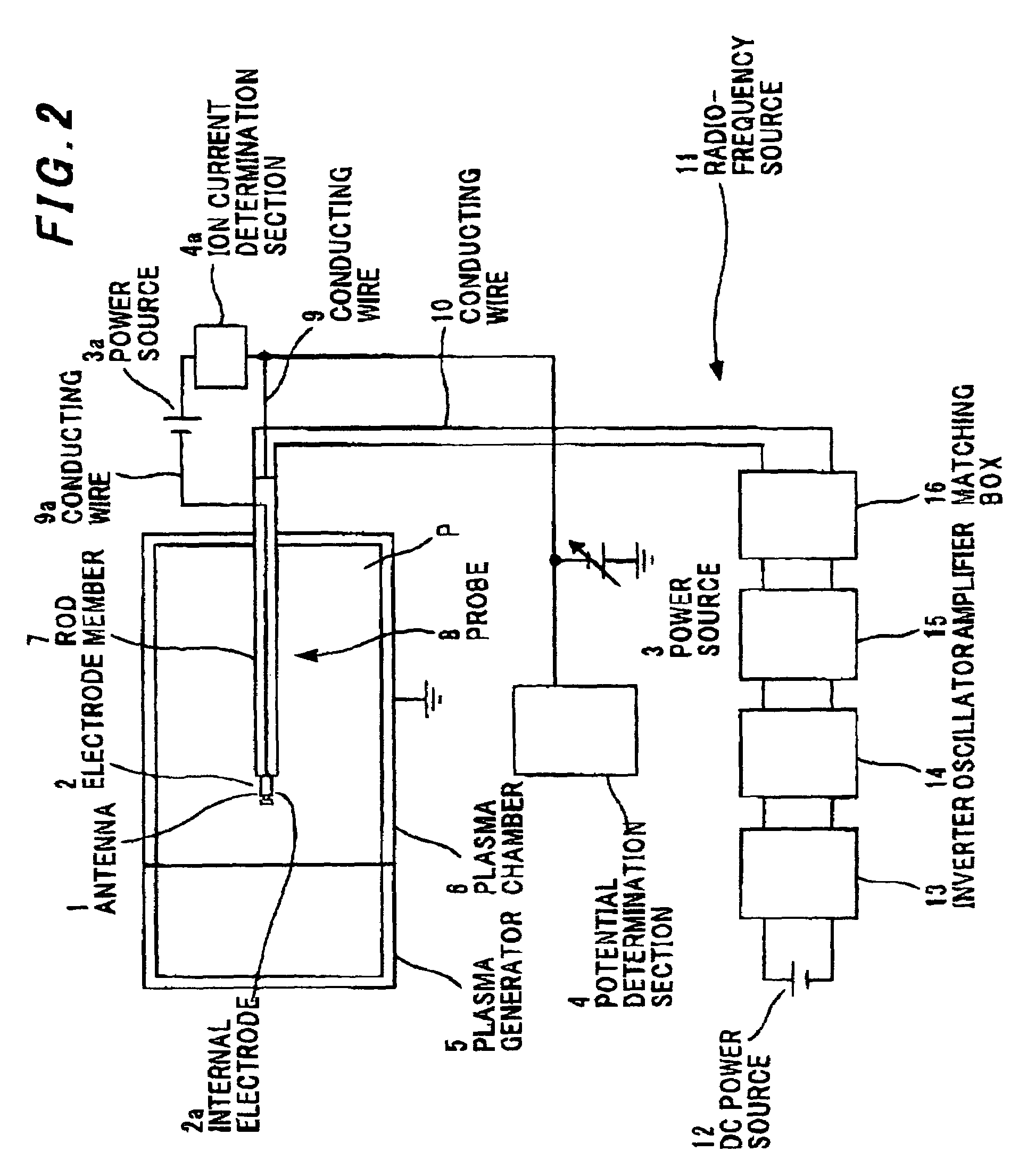
[0036]FIG. 2 is a system diagram showing a plasma potential measuring apparatus in the preferred embodiment according to the invention.

[0037]As shown in FIG. 2, the plasma potential measuring apparatus of the invention is composed of: an antenna 1 that forms a measurement space (See FIG. 5) surrounded by radio-frequency electric field E in plasma atmosphere P; an electrode 2 and an internal electrode 2a that are placed in the measurement space; a power source 3 that controls a potential applied to the electrode 2; a potential determination section 4 that determines as a plasma potential a potential applied when no current is flown into the electrode 2; and an ion current determination section 4a that determines reduction in ion current flown into the internal electrode 2a.

[0038]A plasma chamber 6 is connected to a plasma generator 5 to provide a plasma atmosphere. Thus, plasma generated by the plasma generator 5 is confined in the plasma chamber 6. It is estimated that plasma atmos...


PUM

PropertyMeasurementUnit
lengthaaaaaaaaaa
plasma potentialaaaaaaaaaa
radio-frequency electric fieldaaaaaaaaaa

Abstract

A plasma potential measuring method is conducted by: providing a measurement space surrounded by a radio-frequency electric field in plasma atmosphere; varying a floating potential at an electrode located in the measurement space by the ponderomotive effect acted only on electrons; and determining as a plasma potential a value of the floating potential at the time when an ion current flown into the electrode begins to lower.

Description

[0001]The present application is based on Japanese patent application Nos. 2003-344720 and 2003-344721, the entire contents of which are incorporated herein by reference.BACKGROUND OF THE INVENTION[0002]1. Field of the Invention[0003]The invention relates to a plasma potential measuring method and apparatus, and more particularly to a plasma potential measuring method and apparatus that allows reduction in error factor. The invention also relates to a plasma potential measuring probe, and more particularly to a plasma potential measuring probe that allows accurate measurement in ion current.[0004]2. Description of the Related Art[0005]The emissive probe method is known as a method that allows the measurement of plasma potential in plasma atmosphere without any analysis.[0006]FIG. 1 is a system diagram showing a plasma potential measuring apparatus using the known emissive probe method. As shown in FIG. 1, the emissive probe method is conducted such that a filament 101 in plasma atmo...

Claims


Application Information

Patent Timeline
Patent Type & Authority Patents(United States)
IPC IPC(8): G01N27/62G01R19/00H05H1/00
CPCG01N27/62H05H1/0081G01R19/0061
Inventor ZHANG, XINSATO, NAOYUKIIKEHATA, TAKASHIOGINO, KAZUTOSHI
Owner HITACHI CABLE
Why Eureka
Try Eureka