
Method and apparatus for determining the viability of eggs

a technology for egglaying and viability, applied in the field of methods and apparatus for determining the viability of eggs, can solve the problems of difficult detection of the action or movement of the chick on a light transmission basis, and achieve the effect of increasing the light intensity to unacceptable levels

Inactive Publication Date: 2007-10-30
VISCON BV
View PDF18 Cites 20 Cited by
  • Summary
  • Abstract
  • Description
  • Claims
  • Application Information

AI Technical Summary

Benefits of technology

Enables quick and accurate determination of egg viability throughout the incubation period, reducing the risk of embryo damage and improving the efficiency of resource allocation for vaccination and gender sorting by reliably identifying viable eggs.

Problems solved by technology

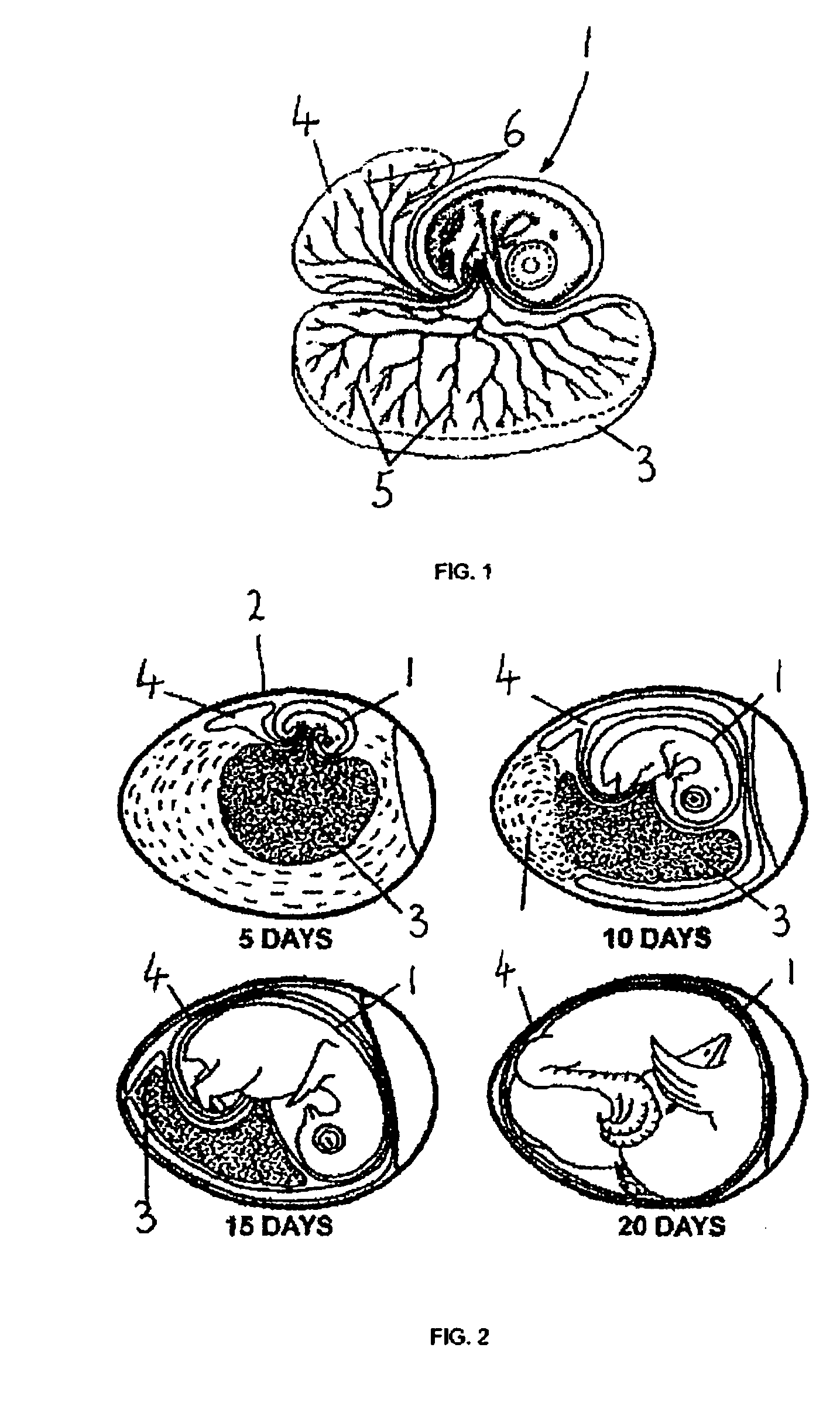
When the egg, for example a poultry egg, is approximately 10-12 days old and older the embryo or chick can be of such an opacity that detection of action of a heart or movement of the chick on a light transmission basis is difficult without increasing the light intensity to unacceptable levels.

Method used


Image

  • Method and apparatus for determining the viability of eggs
  • Method and apparatus for determining the viability of eggs
  • Method and apparatus for determining the viability of eggs

Examples


second embodiment

[0118]Referring to FIGS. 14 and 15 an apparatus generally identified by reference numeral 100 comprises a mount 101 having four arms 102, 103, 104 and 105, equi-circumferentially spaced around a central portion 106. Each arm 102, 103, 104 and 105 is of arcuate shape, constructed from plastics material and pivotally mounted on the central portion 106. Each arm 102, 103, 104 and 105 can pivot independently about a respective projection on the central portion 106. Each arm is also biased downwardly (in the sense of FIG. 14) by a respective spring (not shown) whose function will be described in greater detail below. At the end of each arm 102, 103, 104 and 105 is a surface mount infra-red light source 107, 108, 109 and 110. Each infra-red light source is part number SMT940 manufactured by Epitex, Inc., available from Pacer Components, Berkshire England, that can emit IR with peak intensity at 9.4×10⁻⁷ m (940 nm) and has a half-width of 50 nm. Mounted in the central portion 106 is a prox...

first embodiment

[0133]At step S6 the routine compares a maximum threshold value against the differences calculated above. The maximum value is determined on the basis of differentiating between signal change due to movement and signal change due to heartbeat. As seen in FIG. 18 signal change due to movement will be readily determined on an amplitude basis. If the differences correspond to a voltage difference of more than a few tenths of a volt, then it can be assumed that the signal is due to movement and not heart rate. If so, the routine proceeds to step S5 and generates an output indicating that the egg is viable. If however, all of the differences are found to be below the maximum threshold value then the time at which value number 6 (i.e. the start of the turning point) was taken is stored in memory at step S7. Due to the criteria applied in step S3 above, this will only occur when substantially all of the maximum or minimum turning point is within the window. If, for example, there are two p...


PUM

PropertyMeasurementUnit
angleaaaaaaaaaa
angleaaaaaaaaaa
angleaaaaaaaaaa

Abstract

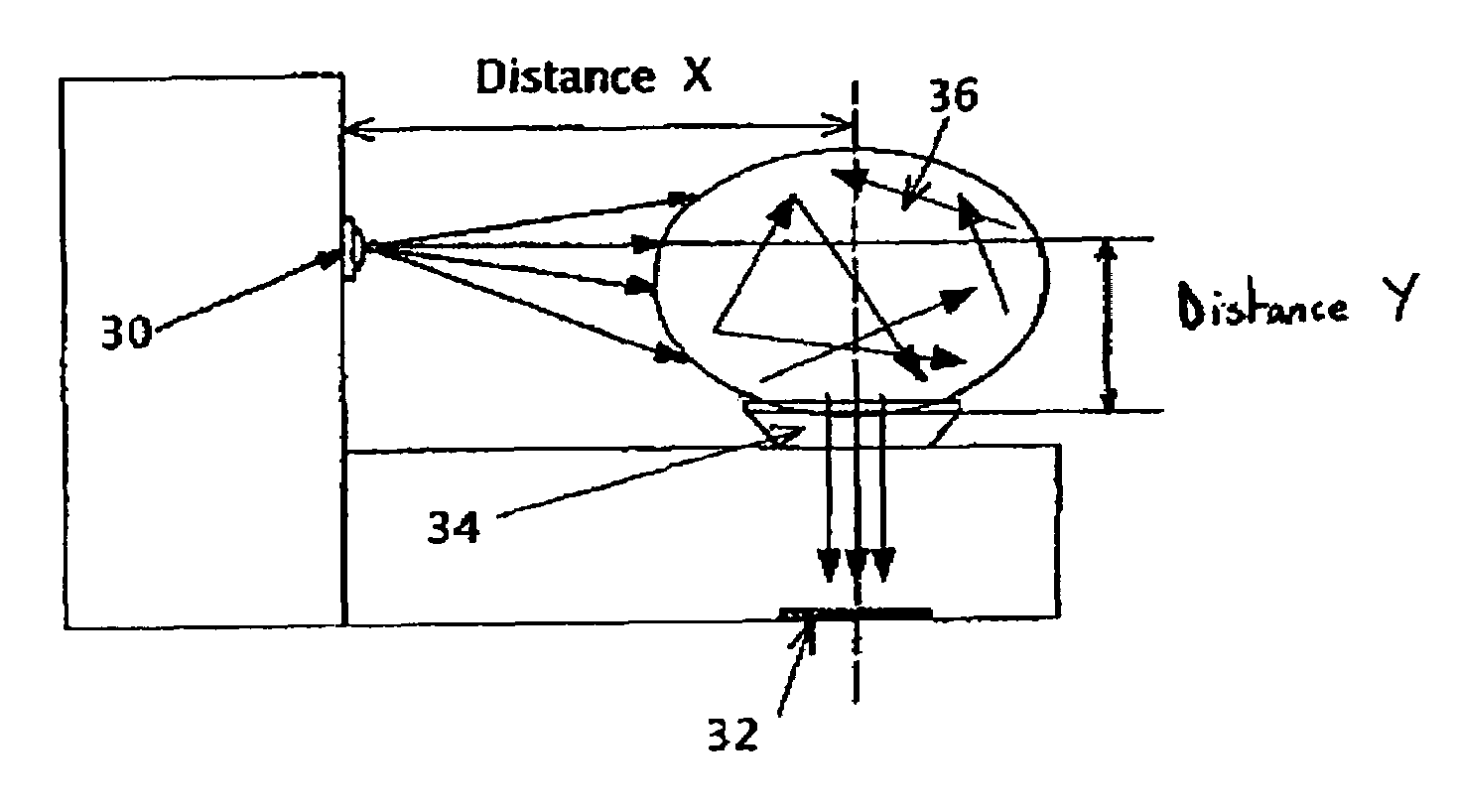
Determining the viability of an egg by:(a) causing electromagnetic radiation, having one or more wavelengths in the infra-red part of the spectrum, to impinge upon the egg;(b) receiving at least a part of the infra-red radiation that has passed through the egg and generating an output signal representative of the received infra-red radiation; and(c) processing said output signal to determine whether there is a cyclical variation in the intensity of the infra-red radiation leaving the egg corresponding to action of a heart, the existence of said cyclical variation indicating that the egg is viable;wherein step (a) is performed by directing infra-red radiation so that it passes through the shell for reflection from an outer surface of a vascular structure adjacent an inner surface of said shell, and step (b) is performed by receiving any infra-red radiation so reflected.

Description

CROSS-REFERENCE TO RELATED APPLICATIONS[0001]This application is a continuation application of International Patent Application No. PCT / GB2003 / 003869, filed on Sep. 4, 2003, which claims priority from UK Patent Application No. 0220553.2 filed on Sep. 4, 2002. This application is also a continuation-in-part application of U.S. application Ser. No. 10 / 475,229, which entered the national stage in the United States on Oct. 17, 2003 now U.S. Pat. No. 7,154,594 based on International Application No. PCT / GB02 / 01784 filed on Apr. 17, 2002, which claims priority from UK Patent Application No. 0109765.8 filed on Apr. 20, 2001.FIELD OF INVENTION[0002]The present invention relates to a method and apparatus for determining the viability of eggs laid by egg-laying animals, and in particular but not exclusively, to eggs laid by reptiles and birds, for example parrots or poultry, to a method of vaccinating eggs in ovo, to a method of sorting eggs by gender, to an apparatus for determining the viabi...

Claims


Application Information

Patent Timeline
Patent Type & Authority Patents(United States)
IPC IPC(8): A01K43/00G01N21/35G01N33/08
CPCA01K43/00A01K45/007G01N33/085G01N21/474G01N21/49G01N21/359
Inventor REEVES, SIDNEY JAMESSIMPSON, KEITH ANGUS
Owner VISCON BV
Learn More