Fiber optic cables that kink with small bend radii

a technology of fiber optic cables and bend radiuses, applied in the field of fiber optic cables, can solve the problems of affecting reducing the service life of copper cables, so as to achieve small bend radius, small bend radius, and preserve optical performance

Active Publication Date: 2007-10-30
CORNING OPTICAL COMM LLC
View PDF2 Cites 267 Cited by
  • Summary
  • Abstract
  • Description
  • Claims
  • Application Information

AI Technical Summary

Benefits of technology

[0006]Another aspect of the present invention is directed to a fiber optic cable having at least one optical fiber, a first strength member, a core material, and a cable jacket. The core material generally surrounds the at least one optical fiber is deformable for cushioning the at least one optical fiber. The optical fiber is a bend resistant optical fiber, thereby allowing relatively small bend radii for the fiber optic cable while preserving optical performance. The first strength member has a tensile strength and a compressive strength where the tensile strength is greater than the compressive strength so that it may kink with a relatively small bend radius. The cable jacket generally surrounds the core material and allows kinking in a bend radius of about 30 millimeters or less while maintaining a suitable level of optical performance.

Problems solved by technology

However, copper cables have drawbacks because they are large, heavy, and can only transmit a relatively limited amount of data with a reasonable cable diameter.
In other words, subscribers have a limited amount of available bandwidth due to the constraints of copper cables in the communication network.
But certain obstacles exist that make it challenging to route optical fibers / optical cables toward the subscriber.
Moreover, the reliability and robustness of the distribution fiber optic cable may have to withstand the rigors of an outdoor environment.
Further, the craft avoids kinking the fiber optic cable because they understand that kinking the fiber optic cable may result in damage or highly degraded optical performance.
Simply stated, the craft understands that bending fiber optic cables beyond their minimum bend radius can cause significant increases in optical attenuation.
As fiber optic cables push toward the subscriber the end user or installer may not be a highly trained craftsman that understands that bending the fiber optic cable into a relatively small radius can cause significant optical attenuation.

Method used


Image

  • Fiber optic cables that kink with small bend radii
  • Fiber optic cables that kink with small bend radii
  • Fiber optic cables that kink with small bend radii

Examples


Embodiment Construction

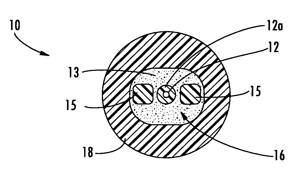
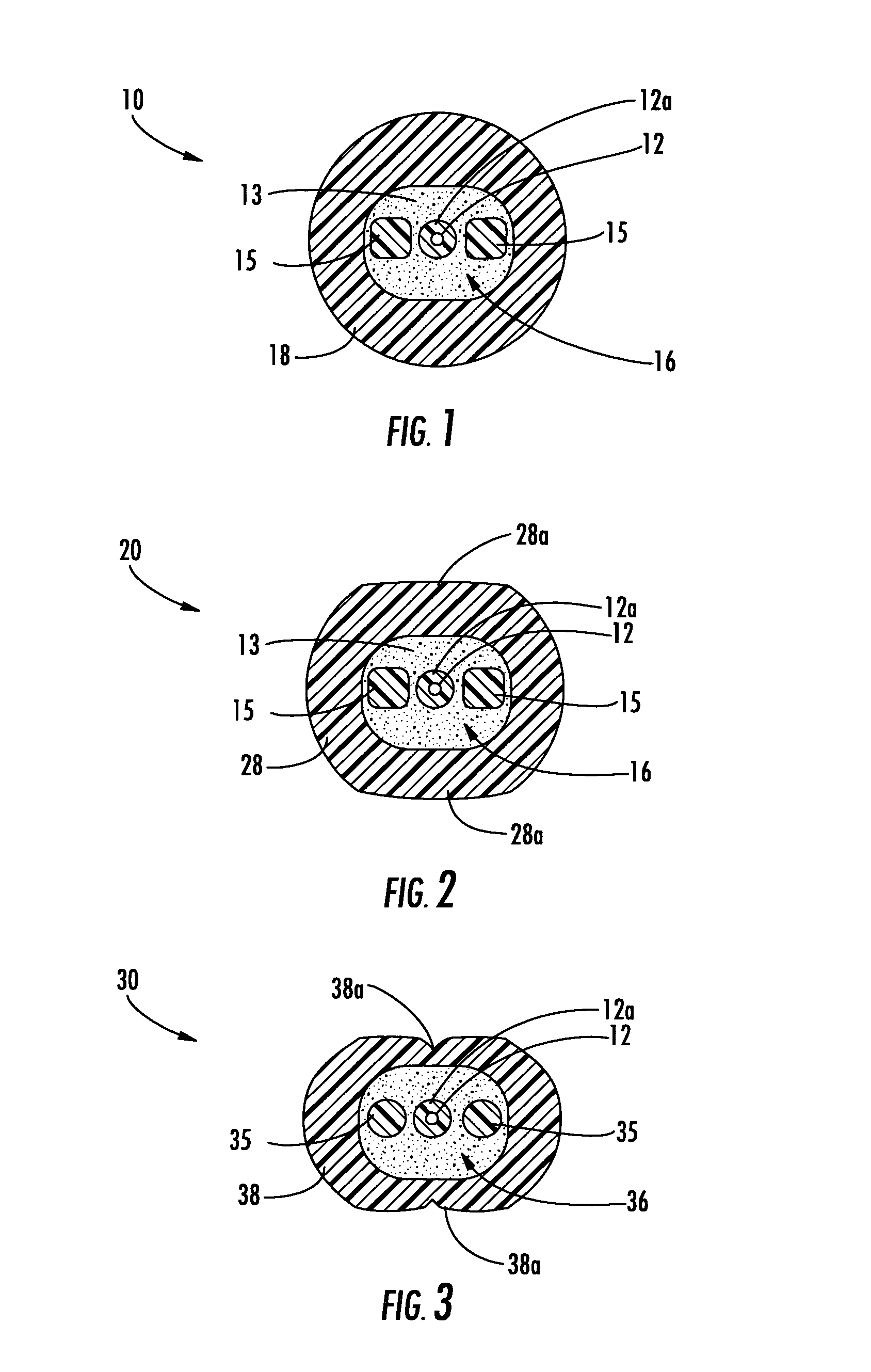
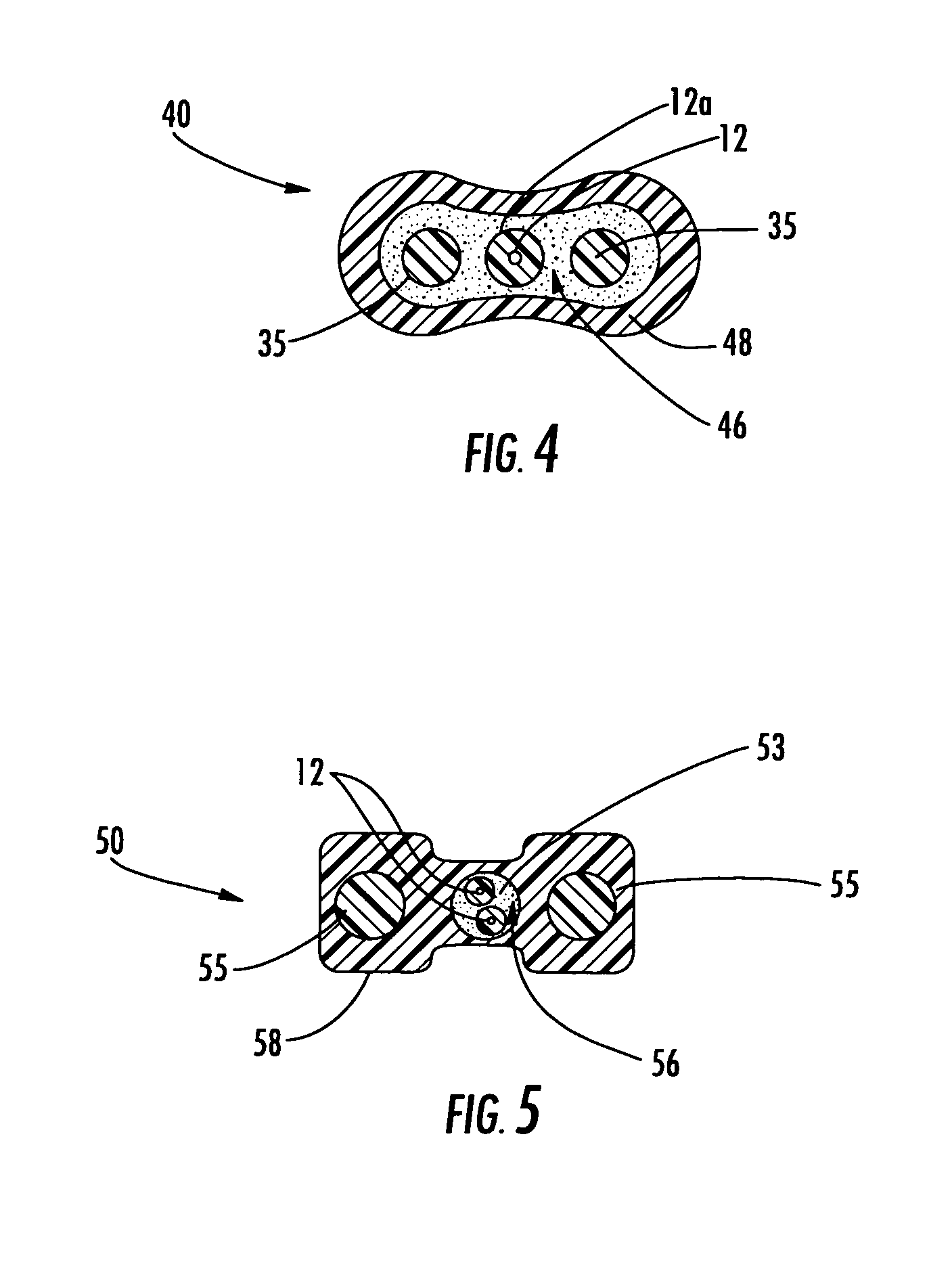
[0016]Reference will now be made in detail to the present preferred embodiments of the invention, examples of which are illustrated in the accompanying drawings. Whenever practical, the same reference numerals will be used throughout the drawings to refer to the same or like parts. FIG. 1 depicts a fiber optic cable 10 according to the present invention. Fiber optic cable 10 includes at least one optical fiber 12 disposed within a cable core 16 that is generally surrounded by a cable jacket 18. Cable core 16 includes a core material 13 and at least one strength member 15. As shown, cable core 16 includes two strength members 15 that are disposed on opposite sides of optical fiber 12. Generally speaking, cable core 16 has a generally oval shape to accommodate strength members 15 on opposite sides of optical fiber 12. Moreover, this arrangement of strength members 15 imparts a preferential bend characteristic to fiber optic cable 10. Fiber optic cables of the present invention are adv...


PUM


Abstract

Fiber optic cables are disclosed that allow a relatively small bend radius and/or may kink while still preserving optical performance. In one embodiment, the fiber optic cable includes at least one optical fiber, a first strength member, a second strength member, a core material, and a cable jacket. The core material generally surrounds the optical fiber, the first strength member, and the second strength member and the core material is deformable for cushioning the optical fiber. The cable jacket generally surrounds the core material and allows a bending radius of about 10 millimeters or less while maintaining a suitable level of optical performance.

Description

FIELD OF THE INVENTION[0001]The present invention relates generally to fiber optic cables used for indoor, outdoor, and / or indoor / outdoor use. More specifically, the present invention relates to fiber optic cables that kink with relatively small bend radii while preserving optical performance.BACKGROUND OF THE INVENTION[0002]Communication networks are used to transport a variety of signals such as voice, video, data transmission, and the like. Traditional communication networks use copper wires in cables for transporting information and data. However, copper cables have drawbacks because they are large, heavy, and can only transmit a relatively limited amount of data with a reasonable cable diameter. Consequently, optical fiber cables replaced most of the copper cables in long-haul communication network links, thereby providing greater bandwidth capacity for long-haul links. However, most communication networks still use copper cables for distribution and / or drop links on the subscr...

Claims


Application Information

Patent Timeline
Patent Type & Authority Patents(United States)
IPC IPC(8): G02B6/44
CPCG02B6/4429
Inventor WAGMAN, RICHARD S.JACKMAN, WILLIAM S.MCALPINE, WARREN W.SEDDON, DAVID A.
Owner CORNING OPTICAL COMM LLC
Why Eureka
Try Eureka