Method and system for using internal data structures for storing information related to remotely monitored devices

a technology for monitoring devices and internal data structures, applied in the field of monitoring devices, can solve the problems of preventing network administrators from obtaining crucial information about the performance and efficiency of devices, affecting the efficiency of monitoring devices, and difficulty in using snmp for monitoring devices, so as to improve the efficiency of monitoring systems

Inactive Publication Date: 2007-10-30
RICOH KK
View PDF16 Cites 65 Cited by
  • Summary
  • Abstract
  • Description
  • Claims
  • Application Information

AI Technical Summary

Benefits of technology

[0015]Information about vendors and models supported by the monitoring system are stored in a database. Using the database to determine the vendors and models supported by the monitoring system allows flexibility in changing the supported vendors and models without actually changing the underlying code. Efficiency of the monitoring system is improved by eliminating multiple accesses of the database in order to determine if each of the monitored devices are supported by the monitoring system. By facilitating retrieval of all the information about the vendors and models of monitored devices supported by the monitoring system by performing minimum number of accesses of the database, and preferably, retrieving the desired information in a single access of the database, the efficiency of the monitoring system is improved. The retrieved information is stored in data structures of a database supported by the monitoring system. A Hypertext Transfer Protocol (HTTP) may be used to access information from the monitored devices.

Problems solved by technology

However, in view of manufacturer differences relating to hardware devices and interfaces, it may be difficult for a monitoring device to communicate with various other devices connected to a network.
Such a disadvantage most likely prevents network administrators from obtaining crucial information about the performance and efficiency of the devices connected to the network.
Using SNMP for monitoring devices is difficult as private MIB's include values that are hard to decipher without a valid key.
Thus, using SNMP, results received from the devices that are being monitored (“monitored devices”), fail to provide a user the status of the monitored devices in a user comprehensible manner.
Further, using SNMP, it is difficult for one to obtain detailed information about a monitored device without a valid key or access to a private MIB to decipher the results obtained as binary or integer values.

Method used


Image

  • Method and system for using internal data structures for storing information related to remotely monitored devices
  • Method and system for using internal data structures for storing information related to remotely monitored devices
  • Method and system for using internal data structures for storing information related to remotely monitored devices

Examples


Embodiment Construction

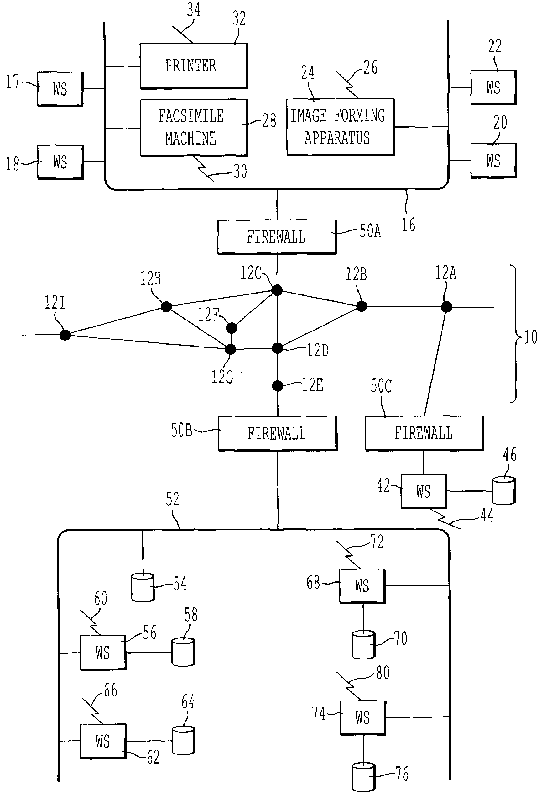
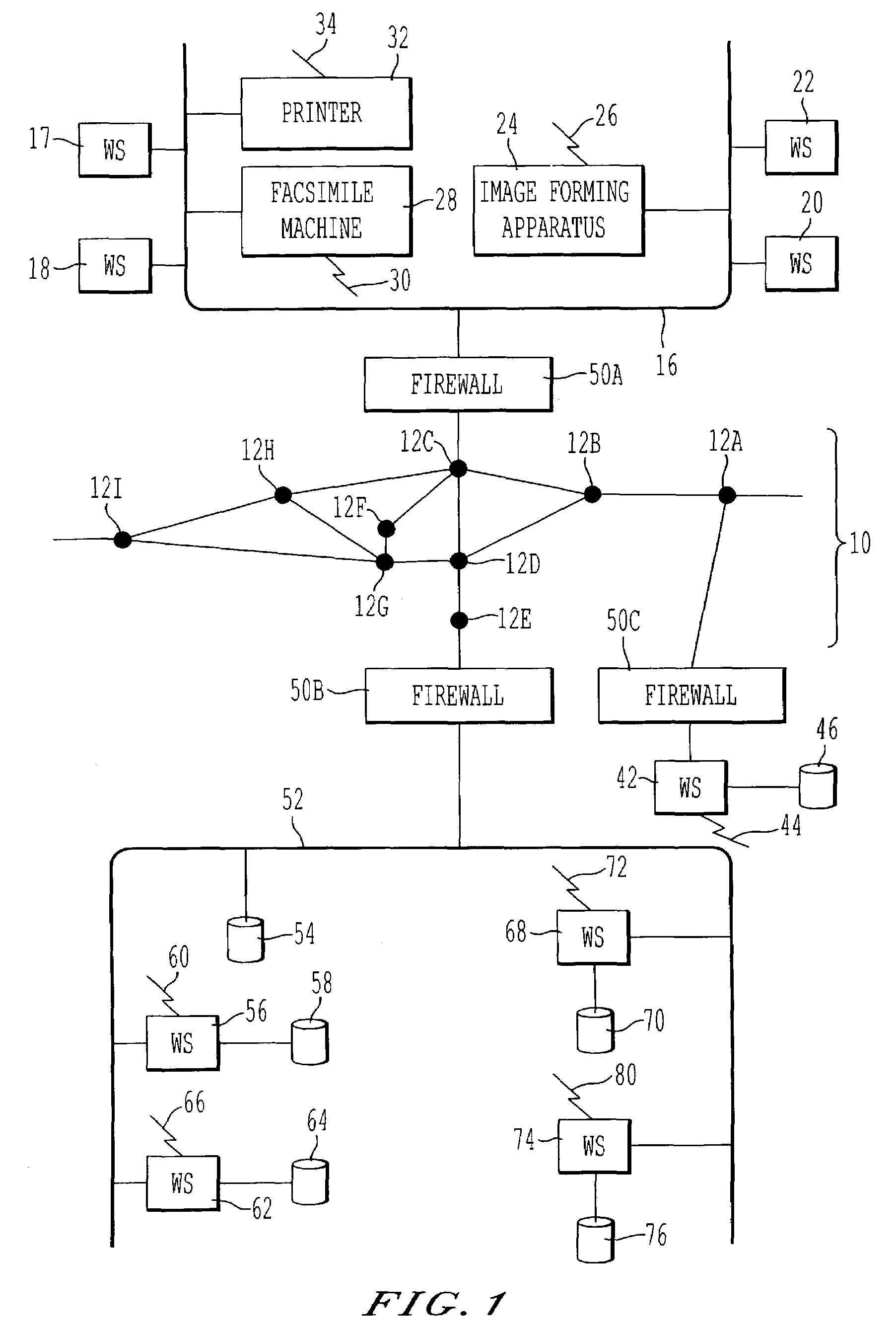
[0058]FIG. 1 illustrates a schematic having various devices and computers for monitoring, diagnosing and controlling the operation of the devices. Specifically, FIG. 1 includes a first network 16, such as a Local Area Network (LAN) connected to computer workstations 17, 18, 20 and 22. The workstations can be any type of computers including, e.g., IBM Personal Computer compatible devices, Unix-based computers, Linux-based computers or Apple Macintoshes. Also connected to the network 16 are a digital image forming apparatus 24, a facsimile machine 28, and a printer 32. As would be appreciated by one of ordinary skill in the art, two or more of the components of the digital image forming apparatus 24 and the facsimile machine 28 can be combined into a unified “image forming apparatus.” For example, the image forming apparatus 24, facsimile machine 28, and printer 32 and the workstations 17, 18, 20 and 22 may be referred to as machines or monitored devices In some configurations, one or...


PUM


Abstract

In a communication system having one or more monitored devices communicatively coupled to a monitoring system, a method of obtaining status information of a monitored device is described. The method includes a) accessing a database having information related to a monitored device; b) retrieving the information from the database; c) populating a map structure with the retrieved information; and d) obtaining the status information from one or more web pages associated with the monitored device using information from the map structure. The method further includes iterating the step of retrieving information from the database in order to obtain the status information until the database has no further information that would be used for extracting status information from the one or more web pages of the monitored device.

Description

CROSS-REFERENCE TO RELATED APPLICATIONS[0001]This application is related to commonly owned co pending U.S. patent application Ser. No. 60 / 359,648 filed Feb. 27, 2002 entitled “Architecture of The Remote Monitoring of Devices Through the Local Monitoring Station and Sending to the Central Station in Which the Multiple Vendors are Supported” which is incorporated herein by reference in its entirety. This application is related to the following commonly owned co pending Applications: U.S. patent application Ser. No. 10 / 225,290 filed Aug. 22, 2002, entitled “Method and System for Monitoring Network Connected Devices with Multiple Protocols”; U.S. patent application Ser. No. 10 / 068,861, filed Feb. 11, 2002, entitled “Method and Apparatus Utilizing Communication Means Hierarchy to Configure or Monitor an Interface Device”; U.S. patent application Ser. No. 10 / 142,989, filed May 13, 2002, entitled “Verification Scheme for Email Message Containing Information About Remotely Monitored Devices...

Claims


Application Information

Patent Timeline
Patent Type & Authority Patents(United States)
IPC IPC(8): G06F17/30G06F17/00
CPCG06Q10/10Y10S707/99933Y10S707/99931
Inventor MOTOYAMA, TETSUROFONG, AVERY
Owner RICOH KK
Why Eureka
Try Eureka